This is a step-by-step documentation of my instrument cluster overhaul project. Not all steps may be applicable to your project. Mine included replacing a malfunctioning speedometer, replacing a defective aftermarket tach (I had originally replaced the vacuum gauge with a tach and it worked for a couple of days and died), and replacing the factory analog gauges and printed circuit boards (PCBs) with new replacements.
I also upgraded the speakers of my RetroSound factory-looking modern audio system by upping the power capability of the stereo dash speaker and adding kick panels and speakers. There are links to everything I bought in the associated step/picture descriptions.
This is the second time I've had the bezel/cluster out of the car and I learned a lot each time. I hope you are able to benefit from my trials and errors if you take this on. Good luck!
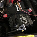
Disconnect battery negative. Don't be that guy, lol.
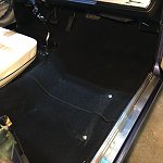
Remove seat(s). This is debatably optional, but there are a lot of tight spaces and contorted positions throughout the procedure. They left no extra room for hands or tools under there. You will ultimately save time and frustration by removing at least the passenger side bucket, but consider removing both. If you have a bench, I wouldn't even try not removing it.
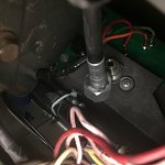
Disconnect the speedometer cable from the rear of the speedo. Reach up under dash from the driver door opening while kneeling outside the car. Unscrew it if it is a '67, un-clip if '68/'69.
Thoroughly tape the bottom of the dash frame to avoid scratches.
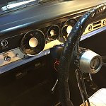
Also tape the top of the column well.
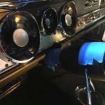
Remove the under-dash trim piece (4 Phillips screws) to gain access to the steering column support structure.
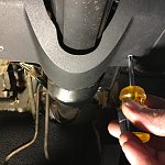
Lower the steering column by removing two 7/16" nuts and one 7/16" bolt from the support bracket. The nuts are closer to the driver seat and the bolt closer to the firewall. Don't confuse these fasteners with the four small bolts that connect the bracket to the column. You want to remove the bracket from the under-dash support structure.
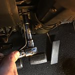
Also loosen the column base collar (two 1/2" bolts). You don't need to completely remove the bolts. The goal is to free up the column enough to drop a bit (it won't come down much). It will drop a max of 1 or 2 inches to make more room to remove the dash bezel.
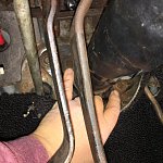
Remove the radio by pulling off the knobs, removing the two front mounting nuts and washers with a deep well socket, and then removing the rear support bracket screwed to the dash behind the radio. Pull the unit out from behind the bezel and disconnect the radio power connector, antenna, and speaker wires. If you have a factory AM radio, it will look slightly different. Pictured is my RetroSound "Redondo" model modern AM/FM stereo with 4 speaker outs, pre-amp outs, and Aux / Twin USB / Bluetooth / SiriusXM capability.
https://www.retromanufacturing.com/
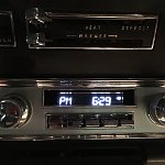
Remove to two chrome knobs from the main heater control levers with a 3/32" hex wrench. Then from underneath the dash, remove the two 3/8" mounting bolts that hold the heater controls to the bezel. It is very tight in there. I found a 3/8" nut driver and really good lighting to be imperative.
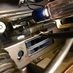
Let the heater controls hang by the cables (no need to remove them) out of the way inside the dash frame.
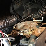
Remove the seven Phillips mounting screws that hold the bezel to the dash frame.
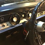
Roll the bezel forward. Be patient and don't force anything. It will roll forward in increments as you disconnect things from it (see the next few pics). Much of it can be disconnected from underneath (on your back) if you prefer, but I've found it easier to work from an upright sitting position through the opening at the top. This is where leaving the driver bucket in can be useful.
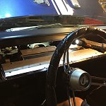
Disconnect the dash lighting connector (three pins, thin rectangular connector at the top of the cluster a little left of the steering column).
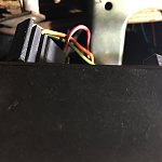
Disconnect the flasher switch connector (top left)
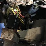
Disconnect the headlight switch connector (just below the flasher switch).
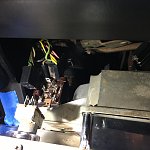
Disconnect the wiper switch (three separate connectors clustered together behind the switch).
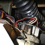
Disconnect the circular connector from the back center of the main cluster PCB (just below the ammeter wires)
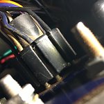
This is the best picture I could get of the ammeter connections. Two heavy gauge wires (black on top, red just beneath and to the left). The space is very tight for removing these (see next two pics). You can just barely fit a small box end 3/8" wrench in through the top opening
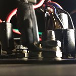
You can just barely fit the box end of a small 3/8" wrench in through the opening created by rolling the bezel forward. **See the updated pics toward the end of this post for an alternative to using the wrench**
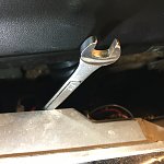
Shows the wrench on the red wire nut after the black wire has been removed. The black wire was connected to the post just in front of where the wrench is. Note the difference between the nuts on the two empty posts shown. The post closer to you in this view has a sheet metal nut, not a standard nut. It is important to differentiate these two posts when reconnecting the ammeter wires, because it is easy to put the black wire on the wrong post.
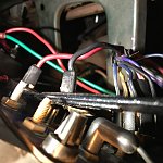
Both ammeter wires and circular connector disconnected.
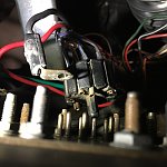
With all connectors/wires removed, the bezel will roll completely forward. There is just enough room to gently slide the cluster out of the car toward the driver door. Be extremely careful and don't force it. Use finesse and be careful not to hit the thin fascia piece that meets the glove box on anything. It is super easy to break that piece.
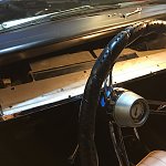
Bezel successfully removed. Shows the areas I taped well before beginning.
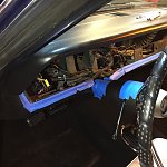
A view of the speedo cable, cluster lighting connector, flasher switch connector, and headlight switch connectors hanging inside the left side of the dash frame. This emphasizes how little room they left you to work in there.
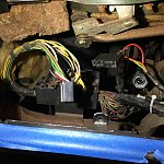
A view of the ammeter wires, circular connector, and wiper switch connectors hanging inside the right of the dash frame. There is more room on this side, so the circular connector and wiper switch can be disconnected from underneath. Not the ammeter though. That has to come loose from the top side.
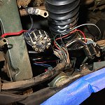
Move the bezel/cluster to a padded bench.
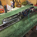
Overview of the rear side of the cluster.
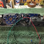
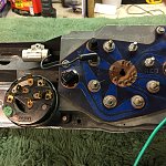
Detail showing the wiper switch, noise suppressor, and main PCB with lighting sockets.
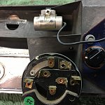
Up-close of the wiper switch and noise suppressor.
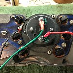
Rear side of the defective tach to be removed. Your cluster may have the "Performance Indicator" (vacuum gauge) mounted here.
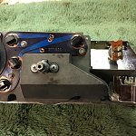
Detail of the right side of the cluster showing the other PCB, speedometer, flasher switch, and headlight switch.
Defective tach removed (three screws).
Aftermarket tach links (two dial face choices):
1967 Dodge Parts | MA1524 | 1967-71 Mopar A-Body Non-Rallye In-Dash Tachometer With 0 @ 8 O'Clock | Classic Industries
1967 Dodge Parts | MA1525 | 1967-71 Mopar A-Body Rallye In-Dash Tachometer With 0 @ 5 O'Clock | Classic Industries
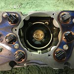
I noted the empty bezel mounting holes in relation to the cluster mounting bolts so as not to confuse them upon reassembly.
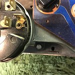
The other empty mounting hole toward the headlight switch.
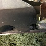
How in blazes does the headlight knob come off? (see next pic)
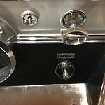
Push this button and the knob and shaft slide out of the switch.
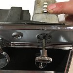
Now remove the headlight switch by gently unscrewing the bezel from the front with small needle nose pliers or a small screw driver.
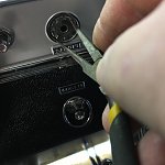
Also unscrew the trip meter knob if present
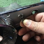
Then remove the wiper switch the same way you removed the headlight switch
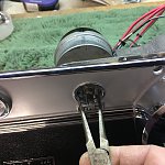
Keep track of everything for reassembly
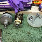
Remove the small cluster mounting bolts and gently separate the cluster from the bezel. Be sure to clean the lenses. I have been told that cleaning the lenses with Meguiar's Gold Class Rich Leather Cleaner and Conditioner works beautifully on the plastic lenses. It also cleans the blue plastic light bulb cups.
https://www.napaonline.com/en/p/NCB...ECS52nMkMkJGMskDlBo3xd9R5zagOjBMaAuI8EALw_wcB
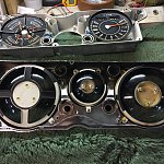
Again, keep track of all the bits and pieces.
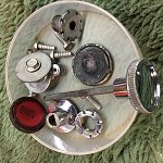
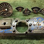
These are the factory gauges that I bought replacements for. The gauges are unbolted (two nuts/posts each) from the rear of the cluster main PCB.
67-71 A BODY RALLYE DASH GAUGE SET [CS213-6] - $399.95 : Charger Specialties, USA Made Gauges, Tachometers and Hood Indicators
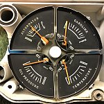
My speedometer was also malfunctioning and needed to be repaired/replaced, so I removed all of it. The speedo is removed with two Phillips screws.
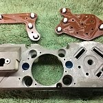
Factory PCBs had peeling contact surfaces around many of the lamp sockets and some of the pins were sketchy, so I bought replacements.
67-71 A BODY BARRACUDA, DUSTER, DEMON CIRCUIT BOARD [CSCQ8] - $99.95 : Charger Specialties, USA Made Gauges, Tachometers and Hood Indicators
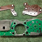
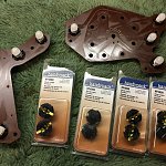
New PCBs installed. Old PCBs still have LEDs installed.
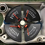
New gauges installed. Follow manufacturer's instructions carefully to ensure the posts are isolated from the metal cluster housing. They employ nylon washers and different nuts on each set of two posts.
The new gauges came with a solid state voltage limiter (or IVR - instrument voltage regulator). I removed the noise suppressor and mounted the new IVR in it's place. I wired the IVR according to the manufacturer's wiring diagram, but I had to make one of the leads longer (soldered and shrink wrapped).
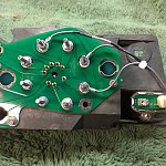
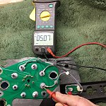
I used a 12V power supply and a digital multi-meter to test the output of the limiter at each gauge post.
Troubleshooting the speedometer. It had a major mechanical issue where the U-shaped bracket that is supposed to free-spin around the wheel was bent and hitting the housing. This pic shows my attempt to re-shape it.
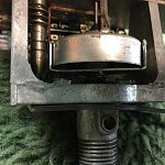
First test of "repaired" speedo. Yeah that didn't do it.
Second test of the speedo after more fiddling with the bracket. Better.
Close-up of the bracket and wheel spinning. Not good enough to consider reliable, so I am replacing it with a spare.
Added a wire to feed 12V to the replacement tach from the limiter feed (there was a handy extra blade terminal on the limiter).
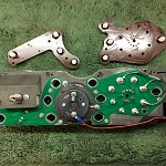
I bought replacement LEDs and lamp sockets from Rock Auto.
LED link: More Information for PHILIPS 158WLED
Sockets link: More Information for ACDELCO LS132
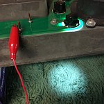
It is imperative to bench test each LED prior to reinstalling the cluster/bezel. The LEDs are polarity sensitive and will only work if installed correctly. I used a 12V power supply, but you could also use a 9V battery.
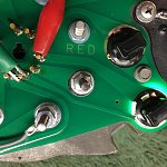
7 of the 8 LEDs are grounded by the cluster housing, but this one has an isolated ground through the circular connector.
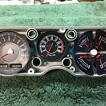
Replacement speedometer, tach and gauges installed. Speedo needle is looking shabby and needs a touch up.
I bought some fluorescent orange model paint from a hobby store to do the touch up.
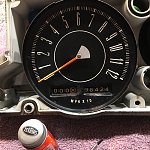
Painting the needle. Thanks, yes I like my green nails too. But seriously, since my wife is an artist and has a steadier hand, she did the the first coat. Not that it really takes all that much precision.
Needle looking much better.
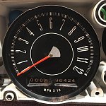
Speedo needle matches the new gauges nicely now.
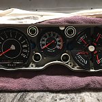
Cluster and bezel reassembled and ready for another complete bench test before reinstallation. Reassembly is the reverse of disassembly.
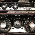
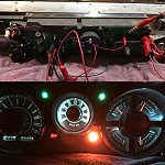
I used the power supply and a bunch of clip leads to light everything at once while it was still on the bench. I learned the hard way the last time I had the cluster out how important the bench testing is. I can't stress it enough lol.
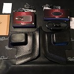
Before I reinstall the cluster, I am upgrading the speakers on RetroSound system. I bought a higher powered stereo dash speaker (uses factory mount) and new kick panels and 4 x 6 speakers for those. I also bought sound dampening mats for the kick panels (all from retromanufacturing.com).
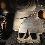
Before removing the dash speaker, disconnect the driver side air hose from the heater box to give you more room.
Remove the two factory mounting plate nuts (circled), not the four speaker mounting nuts (X'd). This is much easier than doing the opposite.
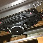
New speaker transferred to factory mounting plate.
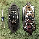
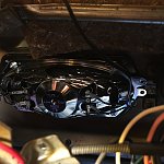
New speaker installed.
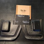
Assembled speakers and kick panels.
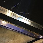
Remove the door sill plates to enable kick panel removal.
Old kick panel comes out with one screw.
Looking at installing the sound dampening mats. I didn't like the fitment and did not feel like cutting it to fit. I'm lazy and the adhesive looked messy...
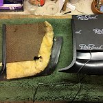
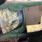
...so I swapped the old insulation to the new kick panels.
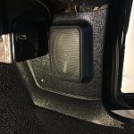
New kick panel installed.
Time to prep the cluster for re-installation. I added a 12V gauge supply wire and tach signal wire.
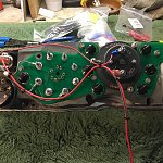
Rehabbed cluster and bezel returned to the car. Carefully wiggle it back into the rolled forward position. The rest of the project is essentially the reverse of removal, but I went ahead and took pics anyway, because I am committed lol.
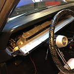
Reconnect wiper switch connectors (three).
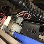
Reconnect ammeter wires and circular connector. Make absolutely sure the red and black wires are on the correct posts*.
As for the circular connector, here is where I ran into my first distressing issue. The pins on the new PCB seemed slightly larger than the old. And of course there is going to be a little variation in placement and maybe all the pins are not completely true, so the circular connector DID NOT want to go back on easily. I fussed with it for a long time and finally got it connected well enough. It is not fully seated, but it is solidly connected. I am fairly confident it will not work it's way loose. Fingers crossed because that was as good as it gets.
*UPDATE: It was confirmed by the Charger Specialties that the ammeter included in the gauge set linked above in fact has the ammeter posts reversed from the factory gauge. They indicated that this detail was not apparent when they took over manufacturing the gauges from the company they bought. They are working to improve the instructions that come with the gauge set, but if you are installing this replacement ammeter, BE SURE to reverse the heavy gauge red and black wires from the original installation and NOT connect them how they are pictured here. I now have to remove the cluster again to correct this.
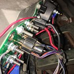
Reconnect headlight switch.
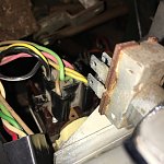
Reconnect flasher switch.
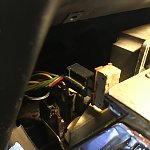
Reconnect cluster lighting connector (TO BE CONTINUED...)
Reconnected cluster/bezel rolled back into place for an initial test...
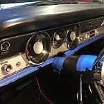
Test of cluster installation with the car running. I found a couple of issues...
Everything worked except the left side dash lights were intermittent. What I found after a lot of dinking around is that the pins on the lighting connector had the same issue as the circular connector (ill fitting). Because there is so little slack on this connector, the only solution was to remove the pins from the connector and install them individually (there turned out to be more to say about this later; added as an update toward the end of this post).
I also noted the ammeter reading discharge. I have received some information that indicates that the new ammeter may have the posts REVERSED. I need to call the manufacturer to confirm. If that is the case, I will need to pull the bezel again to reverse the wires.
 I will update this post when that has been sorted out. This is potentially a HUGE issue, so check back before you do your installation if you are swapping the gauges...
*UPDATE: It was confirmed by the Charger Specialties that the ammeter included in the gauge set linked above in fact has the ammeter posts reversed from the factory gauge. They indicated that this detail was not apparent when they took over manufacturing the gauges from the company they bought. They are working to improve the instructions that come with the gauge set, but if you are installing this replacement ammeter, BE SURE to reverse the heavy gauge red and black wires from the original installation. I now have to remove the cluster again to correct this.
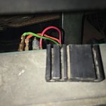
Power supply to new gauges was tapped at the ignition switch by stripping a small section of the blue/white (IGN/RUN) wire and soldering the new red supply wire to it.
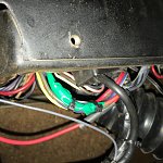
Carefully reconnect speedometer. BE CAREFUL not to over-tighten. Finger tight is what you want.
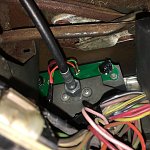
New speakers needed to be wired to the audio system.
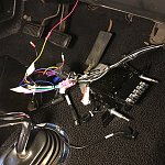
Reposition the heater controls in the bezel by carefully sliding the levers back into the slots. You will probably need to slide them back-and-forth to find the right position of each lever that will allow the controls to slide in easily. As always, don't force anything.
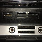
More contortionism required to reinstall the heater control mounting bolts. Don't forget to re-install the two chrome knobs on the front with a 3/32" hex wrench. Hopefully they haven't gone missing lol.
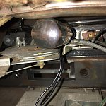
Heater control knobs re-installed. Time to reinstall the radio.
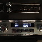
Move the steering column back into position and reattach bracket to support with 2 nuts and 1 bolt.
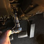
Tighten the column base collar bolts.
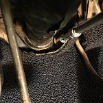
Re-install the under-dash trim piece (4 Phillips screws).
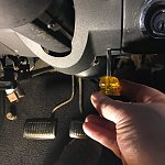
Reinstall seat(s).
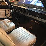
Test the rockin' of the upgraded audio system. I forgot how to set the clock lol.
One test was not enough. Good luck with your project.
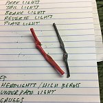
UPDATE: At the end of my first installation of the bezel/cluster, upon the first key test, there was an ominous puff of smoke, and a good portion of the interior went dark. Initial inspection after I disconnected the battery again showed that I had inadvertently (i.e., in my weary rush to finish) routed the 12V gauge supply wire and tach signal wire through the steering column support structure. This didn't show up in my initial engine running test because I had not yet bolted the column back into place. It did not take me long to figure out what I had done and that I now needed to essentially start over. These are the sections of wire that were compromised. The good news is that I eventually determined that none of my new gear had been damaged (more on the troubleshooting in the next pic) and that things could have been way worse. Also seen in the pic is my first scratching out of a list of things working and not working in the car.
I had also noted during previous tests that the new ammeter was reading DISCHARGE (more on this later...).
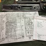
The first thing I did after the unfortunate incident was to check all of the fuses in the block for continuity with a multi-meter. They all tested good, which was disheartening, because I assumed at that point I had done some severe damage. But I took a step back, got some sleep, and started back on it the next day with a good wiring diagram (click here: Wiring Diagrams (Shared)), an updated and complete list of all the affected circuits, and a hard-earned (after many, many years as not only a home garage monkey, but also professionally as an electrical engineer) attitude toward troubleshooting that starts with all the facts and sets aside guesses and assumptions. It is worth reminding you at this point that I had already checked all the fuses...
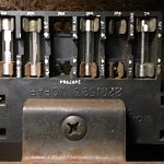
My analysis of all the facts and the wiring diagram lead me straight to the fuse block as a starting point. Within minutes, I had identified that the TAIL/STOP-DOME 20A fuse (second from right empty position in the pic) was INTERMITTENT. Not blown, but one of the terminal ends was loose. This was only apparent after removing and inspecting the fuse. This one fuse was the cause of power loss to ALL the non-working circuits from my list. This situation is unique to classic cars, because modern cars would never have so many devices supplied by a single fuse. I also noted the corroded fuse contacts in the block and that the top side of the fuse block was incredibly dirty. I used an air compressor to blow out all of the dirt, cleaned up all the contacts with contact cleaner and a wire brush, and replaced all of the fuses with new ones.
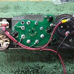
The 12V gauge supply and tach signal wires needed replacing. The third wire shown in the pic is a jumper between the IVR 12V supply and the 12V input to the aftermarket tach.
During this installation, I found a new way to position the bezel/cluster assembly within the dash frame to allow better access to the main PCB and ammeter wires. If you gently slide the left (headlight switch) end of the assembly into the dash frame, you can tilt the right side toward you without damaging anything. It is much easier to access the circular connector and ammeter connections this way.
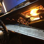
This pic shows the better access to the ammeter wires. I was able to use a small deep-well socket instead of the awkward box end of a 3/8" wrench shown earlier in this post.
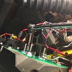
IMPORTANT if you are installing a new Charger Specialties ammeter - the posts are reversed from the factory gauge - so the leads need to be reversed as shown in this pic. My gauge set did not come with any indication that this was the case. I called and confirmed with the manufacturer that the posts are indeed reversed. Even the tech who builds the gauge sets had to research it lol.
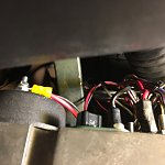
I also found a bit more room to seat the cluster lighting wires. I re-installed the connector instead of the individual removed pins as was done earlier.
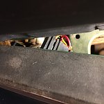
SUCCESS! This is the final test of the gauge cluster and LEDs after completing the second installation. I hope to not have to remove this again for quite some time.
I also upgraded the speakers of my RetroSound factory-looking modern audio system by upping the power capability of the stereo dash speaker and adding kick panels and speakers. There are links to everything I bought in the associated step/picture descriptions.
This is the second time I've had the bezel/cluster out of the car and I learned a lot each time. I hope you are able to benefit from my trials and errors if you take this on. Good luck!
Disconnect battery negative. Don't be that guy, lol.

Remove seat(s). This is debatably optional, but there are a lot of tight spaces and contorted positions throughout the procedure. They left no extra room for hands or tools under there. You will ultimately save time and frustration by removing at least the passenger side bucket, but consider removing both. If you have a bench, I wouldn't even try not removing it.

Disconnect the speedometer cable from the rear of the speedo. Reach up under dash from the driver door opening while kneeling outside the car. Unscrew it if it is a '67, un-clip if '68/'69.

Thoroughly tape the bottom of the dash frame to avoid scratches.

Also tape the top of the column well.

Remove the under-dash trim piece (4 Phillips screws) to gain access to the steering column support structure.

Lower the steering column by removing two 7/16" nuts and one 7/16" bolt from the support bracket. The nuts are closer to the driver seat and the bolt closer to the firewall. Don't confuse these fasteners with the four small bolts that connect the bracket to the column. You want to remove the bracket from the under-dash support structure.

Also loosen the column base collar (two 1/2" bolts). You don't need to completely remove the bolts. The goal is to free up the column enough to drop a bit (it won't come down much). It will drop a max of 1 or 2 inches to make more room to remove the dash bezel.

Remove the radio by pulling off the knobs, removing the two front mounting nuts and washers with a deep well socket, and then removing the rear support bracket screwed to the dash behind the radio. Pull the unit out from behind the bezel and disconnect the radio power connector, antenna, and speaker wires. If you have a factory AM radio, it will look slightly different. Pictured is my RetroSound "Redondo" model modern AM/FM stereo with 4 speaker outs, pre-amp outs, and Aux / Twin USB / Bluetooth / SiriusXM capability.
https://www.retromanufacturing.com/

Remove to two chrome knobs from the main heater control levers with a 3/32" hex wrench. Then from underneath the dash, remove the two 3/8" mounting bolts that hold the heater controls to the bezel. It is very tight in there. I found a 3/8" nut driver and really good lighting to be imperative.

Let the heater controls hang by the cables (no need to remove them) out of the way inside the dash frame.

Remove the seven Phillips mounting screws that hold the bezel to the dash frame.

Roll the bezel forward. Be patient and don't force anything. It will roll forward in increments as you disconnect things from it (see the next few pics). Much of it can be disconnected from underneath (on your back) if you prefer, but I've found it easier to work from an upright sitting position through the opening at the top. This is where leaving the driver bucket in can be useful.

Disconnect the dash lighting connector (three pins, thin rectangular connector at the top of the cluster a little left of the steering column).

Disconnect the flasher switch connector (top left)

Disconnect the headlight switch connector (just below the flasher switch).

Disconnect the wiper switch (three separate connectors clustered together behind the switch).

Disconnect the circular connector from the back center of the main cluster PCB (just below the ammeter wires)

This is the best picture I could get of the ammeter connections. Two heavy gauge wires (black on top, red just beneath and to the left). The space is very tight for removing these (see next two pics). You can just barely fit a small box end 3/8" wrench in through the top opening

You can just barely fit the box end of a small 3/8" wrench in through the opening created by rolling the bezel forward. **See the updated pics toward the end of this post for an alternative to using the wrench**

Shows the wrench on the red wire nut after the black wire has been removed. The black wire was connected to the post just in front of where the wrench is. Note the difference between the nuts on the two empty posts shown. The post closer to you in this view has a sheet metal nut, not a standard nut. It is important to differentiate these two posts when reconnecting the ammeter wires, because it is easy to put the black wire on the wrong post.

Both ammeter wires and circular connector disconnected.

With all connectors/wires removed, the bezel will roll completely forward. There is just enough room to gently slide the cluster out of the car toward the driver door. Be extremely careful and don't force it. Use finesse and be careful not to hit the thin fascia piece that meets the glove box on anything. It is super easy to break that piece.

Bezel successfully removed. Shows the areas I taped well before beginning.

A view of the speedo cable, cluster lighting connector, flasher switch connector, and headlight switch connectors hanging inside the left side of the dash frame. This emphasizes how little room they left you to work in there.

A view of the ammeter wires, circular connector, and wiper switch connectors hanging inside the right of the dash frame. There is more room on this side, so the circular connector and wiper switch can be disconnected from underneath. Not the ammeter though. That has to come loose from the top side.

Move the bezel/cluster to a padded bench.

Overview of the rear side of the cluster.

Detail showing the wiper switch, noise suppressor, and main PCB with lighting sockets.

Up-close of the wiper switch and noise suppressor.

Rear side of the defective tach to be removed. Your cluster may have the "Performance Indicator" (vacuum gauge) mounted here.

Detail of the right side of the cluster showing the other PCB, speedometer, flasher switch, and headlight switch.

Defective tach removed (three screws).
Aftermarket tach links (two dial face choices):
1967 Dodge Parts | MA1524 | 1967-71 Mopar A-Body Non-Rallye In-Dash Tachometer With 0 @ 8 O'Clock | Classic Industries
1967 Dodge Parts | MA1525 | 1967-71 Mopar A-Body Rallye In-Dash Tachometer With 0 @ 5 O'Clock | Classic Industries

I noted the empty bezel mounting holes in relation to the cluster mounting bolts so as not to confuse them upon reassembly.

The other empty mounting hole toward the headlight switch.

How in blazes does the headlight knob come off? (see next pic)

Push this button and the knob and shaft slide out of the switch.

Now remove the headlight switch by gently unscrewing the bezel from the front with small needle nose pliers or a small screw driver.

Also unscrew the trip meter knob if present

Then remove the wiper switch the same way you removed the headlight switch

Keep track of everything for reassembly

Remove the small cluster mounting bolts and gently separate the cluster from the bezel. Be sure to clean the lenses. I have been told that cleaning the lenses with Meguiar's Gold Class Rich Leather Cleaner and Conditioner works beautifully on the plastic lenses. It also cleans the blue plastic light bulb cups.
https://www.napaonline.com/en/p/NCB...ECS52nMkMkJGMskDlBo3xd9R5zagOjBMaAuI8EALw_wcB

Again, keep track of all the bits and pieces.

These are the factory gauges that I bought replacements for. The gauges are unbolted (two nuts/posts each) from the rear of the cluster main PCB.
67-71 A BODY RALLYE DASH GAUGE SET [CS213-6] - $399.95 : Charger Specialties, USA Made Gauges, Tachometers and Hood Indicators

My speedometer was also malfunctioning and needed to be repaired/replaced, so I removed all of it. The speedo is removed with two Phillips screws.

Factory PCBs had peeling contact surfaces around many of the lamp sockets and some of the pins were sketchy, so I bought replacements.
67-71 A BODY BARRACUDA, DUSTER, DEMON CIRCUIT BOARD [CSCQ8] - $99.95 : Charger Specialties, USA Made Gauges, Tachometers and Hood Indicators

New PCBs installed. Old PCBs still have LEDs installed.

New gauges installed. Follow manufacturer's instructions carefully to ensure the posts are isolated from the metal cluster housing. They employ nylon washers and different nuts on each set of two posts.

The new gauges came with a solid state voltage limiter (or IVR - instrument voltage regulator). I removed the noise suppressor and mounted the new IVR in it's place. I wired the IVR according to the manufacturer's wiring diagram, but I had to make one of the leads longer (soldered and shrink wrapped).

I used a 12V power supply and a digital multi-meter to test the output of the limiter at each gauge post.

Troubleshooting the speedometer. It had a major mechanical issue where the U-shaped bracket that is supposed to free-spin around the wheel was bent and hitting the housing. This pic shows my attempt to re-shape it.

First test of "repaired" speedo. Yeah that didn't do it.
Second test of the speedo after more fiddling with the bracket. Better.
Close-up of the bracket and wheel spinning. Not good enough to consider reliable, so I am replacing it with a spare.
Added a wire to feed 12V to the replacement tach from the limiter feed (there was a handy extra blade terminal on the limiter).

I bought replacement LEDs and lamp sockets from Rock Auto.
LED link: More Information for PHILIPS 158WLED
Sockets link: More Information for ACDELCO LS132

It is imperative to bench test each LED prior to reinstalling the cluster/bezel. The LEDs are polarity sensitive and will only work if installed correctly. I used a 12V power supply, but you could also use a 9V battery.

7 of the 8 LEDs are grounded by the cluster housing, but this one has an isolated ground through the circular connector.

Replacement speedometer, tach and gauges installed. Speedo needle is looking shabby and needs a touch up.

I bought some fluorescent orange model paint from a hobby store to do the touch up.

Painting the needle. Thanks, yes I like my green nails too. But seriously, since my wife is an artist and has a steadier hand, she did the the first coat. Not that it really takes all that much precision.
Needle looking much better.

Speedo needle matches the new gauges nicely now.

Cluster and bezel reassembled and ready for another complete bench test before reinstallation. Reassembly is the reverse of disassembly.

I used the power supply and a bunch of clip leads to light everything at once while it was still on the bench. I learned the hard way the last time I had the cluster out how important the bench testing is. I can't stress it enough lol.

Before I reinstall the cluster, I am upgrading the speakers on RetroSound system. I bought a higher powered stereo dash speaker (uses factory mount) and new kick panels and 4 x 6 speakers for those. I also bought sound dampening mats for the kick panels (all from retromanufacturing.com).

Before removing the dash speaker, disconnect the driver side air hose from the heater box to give you more room.

Remove the two factory mounting plate nuts (circled), not the four speaker mounting nuts (X'd). This is much easier than doing the opposite.

New speaker transferred to factory mounting plate.

New speaker installed.

Assembled speakers and kick panels.

Remove the door sill plates to enable kick panel removal.

Old kick panel comes out with one screw.

Looking at installing the sound dampening mats. I didn't like the fitment and did not feel like cutting it to fit. I'm lazy and the adhesive looked messy...

...so I swapped the old insulation to the new kick panels.

New kick panel installed.

Time to prep the cluster for re-installation. I added a 12V gauge supply wire and tach signal wire.

Rehabbed cluster and bezel returned to the car. Carefully wiggle it back into the rolled forward position. The rest of the project is essentially the reverse of removal, but I went ahead and took pics anyway, because I am committed lol.

Reconnect wiper switch connectors (three).

Reconnect ammeter wires and circular connector. Make absolutely sure the red and black wires are on the correct posts*.
As for the circular connector, here is where I ran into my first distressing issue. The pins on the new PCB seemed slightly larger than the old. And of course there is going to be a little variation in placement and maybe all the pins are not completely true, so the circular connector DID NOT want to go back on easily. I fussed with it for a long time and finally got it connected well enough. It is not fully seated, but it is solidly connected. I am fairly confident it will not work it's way loose. Fingers crossed because that was as good as it gets.
*UPDATE: It was confirmed by the Charger Specialties that the ammeter included in the gauge set linked above in fact has the ammeter posts reversed from the factory gauge. They indicated that this detail was not apparent when they took over manufacturing the gauges from the company they bought. They are working to improve the instructions that come with the gauge set, but if you are installing this replacement ammeter, BE SURE to reverse the heavy gauge red and black wires from the original installation and NOT connect them how they are pictured here. I now have to remove the cluster again to correct this.

Reconnect headlight switch.

Reconnect flasher switch.

Reconnect cluster lighting connector (TO BE CONTINUED...)

Reconnected cluster/bezel rolled back into place for an initial test...

Test of cluster installation with the car running. I found a couple of issues...
Everything worked except the left side dash lights were intermittent. What I found after a lot of dinking around is that the pins on the lighting connector had the same issue as the circular connector (ill fitting). Because there is so little slack on this connector, the only solution was to remove the pins from the connector and install them individually (there turned out to be more to say about this later; added as an update toward the end of this post).
I also noted the ammeter reading discharge. I have received some information that indicates that the new ammeter may have the posts REVERSED. I need to call the manufacturer to confirm. If that is the case, I will need to pull the bezel again to reverse the wires.

*UPDATE: It was confirmed by the Charger Specialties that the ammeter included in the gauge set linked above in fact has the ammeter posts reversed from the factory gauge. They indicated that this detail was not apparent when they took over manufacturing the gauges from the company they bought. They are working to improve the instructions that come with the gauge set, but if you are installing this replacement ammeter, BE SURE to reverse the heavy gauge red and black wires from the original installation. I now have to remove the cluster again to correct this.

Power supply to new gauges was tapped at the ignition switch by stripping a small section of the blue/white (IGN/RUN) wire and soldering the new red supply wire to it.

Carefully reconnect speedometer. BE CAREFUL not to over-tighten. Finger tight is what you want.

New speakers needed to be wired to the audio system.

Reposition the heater controls in the bezel by carefully sliding the levers back into the slots. You will probably need to slide them back-and-forth to find the right position of each lever that will allow the controls to slide in easily. As always, don't force anything.

More contortionism required to reinstall the heater control mounting bolts. Don't forget to re-install the two chrome knobs on the front with a 3/32" hex wrench. Hopefully they haven't gone missing lol.

Heater control knobs re-installed. Time to reinstall the radio.

Move the steering column back into position and reattach bracket to support with 2 nuts and 1 bolt.

Tighten the column base collar bolts.

Re-install the under-dash trim piece (4 Phillips screws).

Reinstall seat(s).

Test the rockin' of the upgraded audio system. I forgot how to set the clock lol.
One test was not enough. Good luck with your project.
UPDATE: At the end of my first installation of the bezel/cluster, upon the first key test, there was an ominous puff of smoke, and a good portion of the interior went dark. Initial inspection after I disconnected the battery again showed that I had inadvertently (i.e., in my weary rush to finish) routed the 12V gauge supply wire and tach signal wire through the steering column support structure. This didn't show up in my initial engine running test because I had not yet bolted the column back into place. It did not take me long to figure out what I had done and that I now needed to essentially start over. These are the sections of wire that were compromised. The good news is that I eventually determined that none of my new gear had been damaged (more on the troubleshooting in the next pic) and that things could have been way worse. Also seen in the pic is my first scratching out of a list of things working and not working in the car.
I had also noted during previous tests that the new ammeter was reading DISCHARGE (more on this later...).

The first thing I did after the unfortunate incident was to check all of the fuses in the block for continuity with a multi-meter. They all tested good, which was disheartening, because I assumed at that point I had done some severe damage. But I took a step back, got some sleep, and started back on it the next day with a good wiring diagram (click here: Wiring Diagrams (Shared)), an updated and complete list of all the affected circuits, and a hard-earned (after many, many years as not only a home garage monkey, but also professionally as an electrical engineer) attitude toward troubleshooting that starts with all the facts and sets aside guesses and assumptions. It is worth reminding you at this point that I had already checked all the fuses...

My analysis of all the facts and the wiring diagram lead me straight to the fuse block as a starting point. Within minutes, I had identified that the TAIL/STOP-DOME 20A fuse (second from right empty position in the pic) was INTERMITTENT. Not blown, but one of the terminal ends was loose. This was only apparent after removing and inspecting the fuse. This one fuse was the cause of power loss to ALL the non-working circuits from my list. This situation is unique to classic cars, because modern cars would never have so many devices supplied by a single fuse. I also noted the corroded fuse contacts in the block and that the top side of the fuse block was incredibly dirty. I used an air compressor to blow out all of the dirt, cleaned up all the contacts with contact cleaner and a wire brush, and replaced all of the fuses with new ones.

The 12V gauge supply and tach signal wires needed replacing. The third wire shown in the pic is a jumper between the IVR 12V supply and the 12V input to the aftermarket tach.

During this installation, I found a new way to position the bezel/cluster assembly within the dash frame to allow better access to the main PCB and ammeter wires. If you gently slide the left (headlight switch) end of the assembly into the dash frame, you can tilt the right side toward you without damaging anything. It is much easier to access the circular connector and ammeter connections this way.

This pic shows the better access to the ammeter wires. I was able to use a small deep-well socket instead of the awkward box end of a 3/8" wrench shown earlier in this post.

IMPORTANT if you are installing a new Charger Specialties ammeter - the posts are reversed from the factory gauge - so the leads need to be reversed as shown in this pic. My gauge set did not come with any indication that this was the case. I called and confirmed with the manufacturer that the posts are indeed reversed. Even the tech who builds the gauge sets had to research it lol.

I also found a bit more room to seat the cluster lighting wires. I re-installed the connector instead of the individual removed pins as was done earlier.

SUCCESS! This is the final test of the gauge cluster and LEDs after completing the second installation. I hope to not have to remove this again for quite some time.
