You are using an out of date browser. It may not display this or other websites correctly.
You should upgrade or use an
alternative browser.
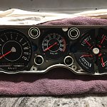
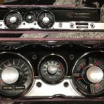
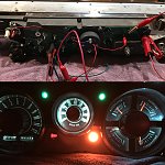
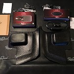
Step-by-Step '67 Rallye Gauge Cluster Overhaul/Audio System Upgrade
-
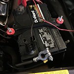
001 - Disconnect Battery.JPG
782.4 KB
· Views: 3,901
-
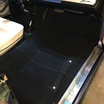
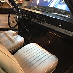
002 - Remove Seat.JPG
872.8 KB
· Views: 679
-
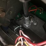
002a - Disconnect Speedometer.JPG
375 KB
· Views: 666
-
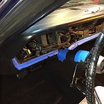
003 - Tape Bottom of Dash Frame.JPG
899 KB
· Views: 705
-
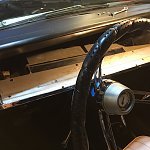
004 - Tape Top of Column.JPG
867.6 KB
· Views: 680
-

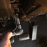
004a - Remove Steering Column by Unbolting Two Mounting Nuts and One Mounting Bolt.JPG
1,023.1 KB
· Views: 628
-
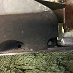
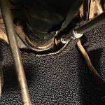
004b - Loosen Two Steering Column Base Bracket Collar Bolts.JPG
822.8 KB
· Views: 637
-
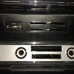
005 - Remove Radio.jpg
211.1 KB
· Views: 698
-
005a - Unbolt Heater Controls (three-eigths nut driver).JPG
1.1 MB
· Views: 634
-
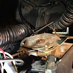
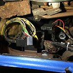
005b - Heater Controls Unbolted and Hanging by Cables.JPG
738.9 KB
· Views: 634
-
006 - Remove Severn Bezel Screws.JPG
878.6 KB
· Views: 698
-
007 - Roll Bezel Forward.JPG
792.6 KB
· Views: 710
-
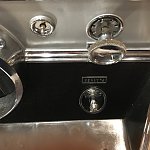
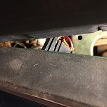
008 - Cluster Lighting Connector.JPG
562.4 KB
· Views: 702
-
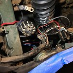
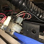
009 - Flasher Switch Connector Above Headlight Switch Connector.JPG
674.7 KB
· Views: 652
-
010 - Flasher and Headlight Switches Disconnected.JPG
716.7 KB
· Views: 654
-
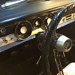
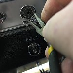
011 - Wiper Switch.JPG
788.7 KB
· Views: 707
-
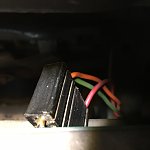
012 - Circular Connector.JPG
626.5 KB
· Views: 691
-
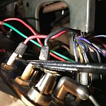
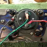
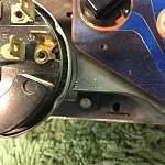
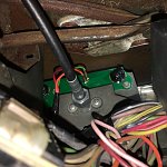
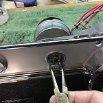
013 - Ammeter Connections.JPG
719.1 KB
· Views: 697
-
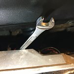
014 - Three-Eights Wrench on Ammeter Nut.JPG
704.8 KB
· Views: 712
-
015 - Three-Eights Wrench on Ammeter Nut (Close Up).JPG
716.4 KB
· Views: 662
-
016 - Ammeter Wires and Circular Connector Removed.JPG
698.5 KB
· Views: 644
-
017 - Bezel Rolled Completely Forward for Removal.JPG
758 KB
· Views: 654
-
018 - Bezel Removed.JPG
838.6 KB
· Views: 740
-
019 - Left Side Connectors Removed.JPG
982.5 KB
· Views: 732
-
020 - Center and Right Side Connectors Removed.JPG
967.9 KB
· Views: 688
-
021 - Remove Bezel to Padded Bench.JPG
1.3 MB
· Views: 769
-
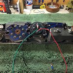
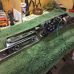
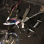
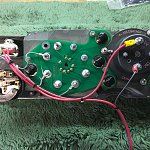
022 - Overview of Rear Side of Cluster.JPG
1.3 MB
· Views: 770
-
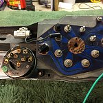
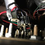
023 - Wiper Switch and CLuster PCB Detail.JPG
1.1 MB
· Views: 775
-
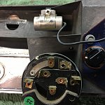
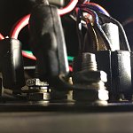
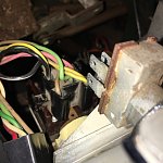
024 - Noise Suppressor and Wiper Switch to be Removed.JPG
1 MB
· Views: 695
-
025 - Defective Tach to be Removed.JPG
971.7 KB
· Views: 715
-
026 - Defective Speedometer and Headlight Switch to be Removed.JPG
1.1 MB
· Views: 675
-
027 - Tach (Vac Gauge) Removed.JPG
930.6 KB
· Views: 711
-
028 - Note Empty Hole for Reassembly.JPG
1.1 MB
· Views: 692
-
029 - Not Empty Hole for Reassembly.JPG
1.1 MB
· Views: 699
-
030 - How do I Remove the Headlight Switch Knob & Unscrew Trip Meter Knob.JPG
813.1 KB
· Views: 648
-
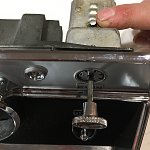
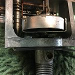
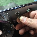
031 - Push This Button.JPG
674.3 KB
· Views: 697
-
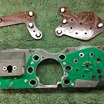
032 - (8 screws) Cluster Separated From Bezel - Lenses Need Cleaning.JPG
1.2 MB
· Views: 672
-
033 - Keep Track of Mounting Hardware.JPG
1.1 MB
· Views: 733
-
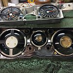
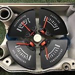
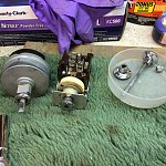
034 - Original Gauges to be Removed.JPG
972.6 KB
· Views: 716
-
035 - Speedometer and Gauges Removed.JPG
1.2 MB
· Views: 717
-
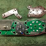
036 - Original PCBs Removed with LEDs Still in Place.JPG
1.1 MB
· Views: 661
-
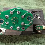
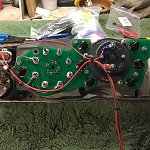
037 - New PCBs mounted.JPG
1.2 MB
· Views: 738
-
038 - New Gauges Mounted.JPG
924.4 KB
· Views: 747
-
039 - Noise Suppressor Removed - New Limiter Installed and Wired.JPG
1 MB
· Views: 694
-
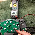
040 - Test New Limiter with PS and DMM.JPG
1.4 MB
· Views: 732
-
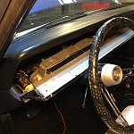
040a - Troubleshooting Malfunctioning Speedo - Binding Mechanism.JPG
754.4 KB
· Views: 672
-
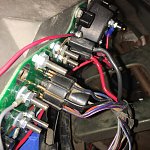
041 - Replacement Tach Wired to 12V at Limiter - Prepped for LED Transfer.JPG
1.2 MB
· Views: 702
-
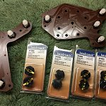
042 - Replacement Lamp Holders.JPG
1.2 MB
· Views: 763
-
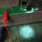
043 - Test each LED with 12V PS.JPG
859.1 KB
· Views: 764
-
044 - This LED has an Isolated GND.JPG
1,004.6 KB
· Views: 738
-
045 - Replacement Speedometer and Tach Installed - Speedo Needle Needs Touch Up.JPG
1.2 MB
· Views: 707
-
046 - Flourescent Orange Model Paint.JPG
1.2 MB
· Views: 721
-
048 - Fresh Paint on the Speedo Needle.JPG
1,008.5 KB
· Views: 718
-
049 - Refreshed Cluster Ready to be Re-Mated with Bezel.JPG
1 MB
· Views: 670
-
050 - Reassembled Cluster and Bezel Ready for Reinstallation.jpg
1.2 MB
· Views: 694
-
051 - Final Bench Test of Powered Tach and LEDs.jpg
1,009.1 KB
· Views: 685
-
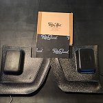
052 - New Kick Panels, Speakers, and Soundproofing Mats.jpg
1 MB
· Views: 680
-
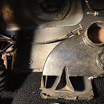
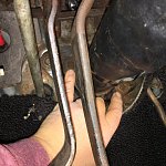
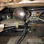
053 - Remove the Driver Side Heater Hose from the Heater Box to Make Room for Speaker Removal.JPG
914.9 KB
· Views: 685
-
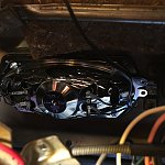
054 - Exisiting Dash Speaker to be Removed.JPG
868.3 KB
· Views: 672
-
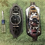
055 - New Speaker Swapped to Mounting Bracket.JPG
1.4 MB
· Views: 671
-
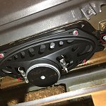
056 - New Speaker Installed.JPG
989.9 KB
· Views: 695
-
057 - New Speakers Mounted to New Kick Panels.JPG
1.2 MB
· Views: 683
-
058 - Remove Door Sills Before Old Kick Panels.JPG
1.3 MB
· Views: 673
-
059 - Old Kick Panels Only Have a Single Screw.JPG
879.8 KB
· Views: 639
-
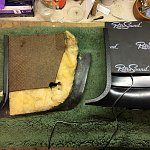
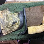
060 - I Didn't Like the Fitment of the Soundproofing Mats I bought.JPG
1.2 MB
· Views: 682
-
061 - I Swapped the Old Insulation to the New Kick Panels.JPG
1.3 MB
· Views: 673
-
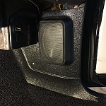
062 - New Kick Panel with Speaker Installed.JPG
1.4 MB
· Views: 698
-
063 - Getting the Cluster Ready to Install by Adding 12V Feed and Tach Signal Wires.JPG
1.1 MB
· Views: 701
-
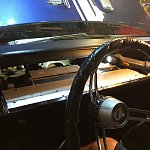
064 - Dash Bezel Moved Back into the Car.JPG
829.8 KB
· Views: 768
-
065 - Wiper Switch Reconnected.JPG
904.5 KB
· Views: 760
-
066 - Circular Connector and Ammeter Wires Reconnected.JPG
1.2 MB
· Views: 669
-
067 - Headlight Switch Reconnected.JPG
887.8 KB
· Views: 726
-
068 - Cluster Lighting Connector Reseated.JPG
434.5 KB
· Views: 721
-
069 - Flasher Switch Reconnected.JPG
834 KB
· Views: 731
-
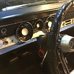
070 - Bezel and Cluster Back in Place for Initial Test.JPG
830.6 KB
· Views: 678
-
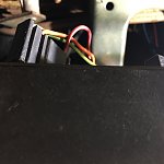
072 - Cluster Lighting Connector Pins Removed.JPG
544 KB
· Views: 640
-
073 - Power Feed to Gauges Tapped into Lighting Circuit at the Ignition Switch (Blue-White Wire).JPG
848.5 KB
· Views: 691
-
074 -Reconnect Speedometer.JPG
749.6 KB
· Views: 719
-
075 - Wire New Speakers to Stereo.JPG
1.1 MB
· Views: 722
-
076 - Reposition Heater Controls.JPG
941.1 KB
· Views: 728
-
077 - Bolt in Heater Controls.JPG
964.4 KB
· Views: 744
-
078 - Remount Steering Column by Installing Two Mounting Nuts and One Mounting Bolt.JPG
1,023.1 KB
· Views: 664
-
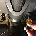
079 - Tighten Two Steering Column Base Bracket Collar Bolts.JPG
1.4 MB
· Views: 659
-
080 - Reinstall Seat.JPG
798.2 KB
· Views: 729
-

125549229_10220901579821805_7032691350699139896_o.jpg
210.6 KB
· Views: 647
-
01.JPG
757.8 KB
· Views: 637
-
01a.JPG
1 MB
· Views: 680
-
02.JPG
832.3 KB
· Views: 675
-
03.JPG
1.3 MB
· Views: 685
-
04.JPG
224.6 KB
· Views: 701
-
05.JPG
1.1 MB
· Views: 698
-
06.JPG
830.9 KB
· Views: 688
-
07.JPG
781.3 KB
· Views: 713
-
08.JPG
592.1 KB
· Views: 695
-
09.JPG
597.2 KB
· Views: 663
-
031a - Remove Headlight Switch Bezel.JPG
846.1 KB
· Views: 624
-
031b - Remove Trip Meter Knob.JPG
546.6 KB
· Views: 647
-
031c - Remove Wipwer Switch Bezel.JPG
991.5 KB
· Views: 652
-
031d - Switches Removed.JPG
1.2 MB
· Views: 670