12 Second N/A Slant 6?
I have utilized "turbo" pistons for the 18cc cup in the crown. The pistons in question are "hypereutectic" cast psitons. They are very strong W/less expansion ratio than forged. That allows running close tolerances on the piston skirt clearance & a longer lasting engine build.
Forced induction engines ususlly utilize low CR in the 8:1 range to allow more room for the compressed air. Think of 2 identical air compressors. One has a 40 gallon tank, the other a 50 gallon tank. Which compressor can store more atmosperic pressure air when it is compressed to a given pressure? The larger volume combustion chamber serves the same purpose.
When the 2.2L turbo piston is utilized in an engine W/4.175 stroke, the designed 8:1ish CR of the original application climbs to the 12:1 CR range.
Indeed I will need to add about 10cc to that cup volume if I am to run 93 octane pump gas.
At 1st I thougt this was feasable but closer examination to the drawing @ the beginning of this thread makes me think otherwise. The cup is flat on the bottom so there is no material left to remove from the already minimal thickness crown. At best I might gain 1 or 2cc, not the 10cc neccessary.
I can not increase the already maginal quench distance to lower CR as that will increase the likelyhood of detonation even though CR is decreased.
It may be neccessary to explore water methanol injection. At 1st I was not able to wrap my mind around how one would control the W/M injection W/O complex plumbing & switches.
Since I have many of the components on hand from a failed attempt to use W/M injection on my '06 Charger 5.7 Hemi, I did not want to spend over $600 for a "kit" that would contain at most $300 worth of compnents, many of wich I already had.
When it looked like W/M was going to be mandatory I expanded my search & found this controler than works on both vacuum & RPM.
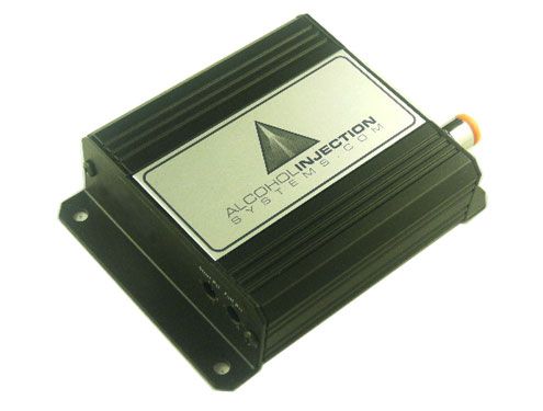
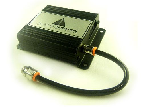
http://www.alcoholinjectionsystems....thanol-Injection-Controller/product_info.html
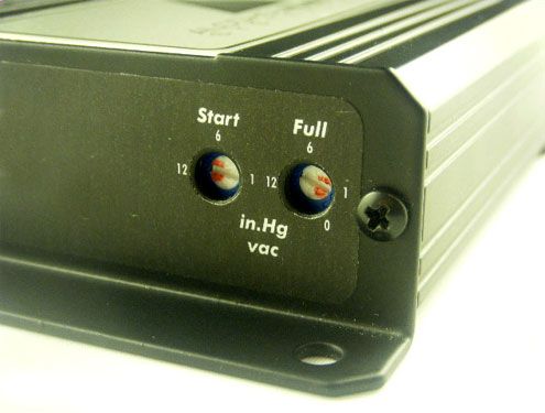
The controller will take care of WM injection during high load conditions, but what about low load & idle?
I found an article about using a large hypodermic needle tip inserted into a carburetor vacuum circuit. This article was concerned primarily W/the fuel economy savings but it will serve our purposes here for spark knock suppression.
Now, since we are no longer limited to 10:1 CR I am thinking along the lines of decreasing the quench hieght to a more desirable .040". That will jump CR up into the 13:1 range.
All of this is speculation until I get some head casting to work with.
If the stock castings will allow a realistic shot @ a 10:1 CR then that is the direction I will go. If not, then quench distance will be optimized to .040" & WM injection will be utilized.
If WM dioesn't work, there's a small airport near me that has high octane aviation fuel as well as 110 octane race fuel @ another source.
I think that I can make WM work. If I can, a 13:1 \6 utilizing WM injection should be able to make in the neighborhood of 300HP.
EDIT: Here is the article on the vacume W/M set-up for low load conditions.
http://www.dave-cushman.net/misc/mannject.html
I have utilized "turbo" pistons for the 18cc cup in the crown. The pistons in question are "hypereutectic" cast psitons. They are very strong W/less expansion ratio than forged. That allows running close tolerances on the piston skirt clearance & a longer lasting engine build.
Forced induction engines ususlly utilize low CR in the 8:1 range to allow more room for the compressed air. Think of 2 identical air compressors. One has a 40 gallon tank, the other a 50 gallon tank. Which compressor can store more atmosperic pressure air when it is compressed to a given pressure? The larger volume combustion chamber serves the same purpose.
When the 2.2L turbo piston is utilized in an engine W/4.175 stroke, the designed 8:1ish CR of the original application climbs to the 12:1 CR range.
Indeed I will need to add about 10cc to that cup volume if I am to run 93 octane pump gas.
At 1st I thougt this was feasable but closer examination to the drawing @ the beginning of this thread makes me think otherwise. The cup is flat on the bottom so there is no material left to remove from the already minimal thickness crown. At best I might gain 1 or 2cc, not the 10cc neccessary.
I can not increase the already maginal quench distance to lower CR as that will increase the likelyhood of detonation even though CR is decreased.
It may be neccessary to explore water methanol injection. At 1st I was not able to wrap my mind around how one would control the W/M injection W/O complex plumbing & switches.
Since I have many of the components on hand from a failed attempt to use W/M injection on my '06 Charger 5.7 Hemi, I did not want to spend over $600 for a "kit" that would contain at most $300 worth of compnents, many of wich I already had.
When it looked like W/M was going to be mandatory I expanded my search & found this controler than works on both vacuum & RPM.


http://www.alcoholinjectionsystems....thanol-Injection-Controller/product_info.html
The controller will take care of WM injection during high load conditions, but what about low load & idle?
I found an article about using a large hypodermic needle tip inserted into a carburetor vacuum circuit. This article was concerned primarily W/the fuel economy savings but it will serve our purposes here for spark knock suppression.
Now, since we are no longer limited to 10:1 CR I am thinking along the lines of decreasing the quench hieght to a more desirable .040". That will jump CR up into the 13:1 range.
All of this is speculation until I get some head casting to work with.
If the stock castings will allow a realistic shot @ a 10:1 CR then that is the direction I will go. If not, then quench distance will be optimized to .040" & WM injection will be utilized.
If WM dioesn't work, there's a small airport near me that has high octane aviation fuel as well as 110 octane race fuel @ another source.
I think that I can make WM work. If I can, a 13:1 \6 utilizing WM injection should be able to make in the neighborhood of 300HP.
EDIT: Here is the article on the vacume W/M set-up for low load conditions.
http://www.dave-cushman.net/misc/mannject.html