66 Dart electronic ignition issues
I took this off the mopar1 site it ain't mine but
I have done the conversion and it works
Below is a diagram showing how to install a 70's Voltage Regulator on a sixties mopar:
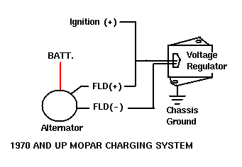 dia. #3
Basically, a wire is added to the second Field brush on the alternator. On the orignal alternator, this brush is grounded to the case of the alternator, so you'll need to either change the alternator to a 1970 or new style, or adapt the newer brush set to the old alternator. The brush set costs about $5 at your local parts store. The second field wire is connected to the outside plug on the newer voltage regulator. (two plugs, one is in the middle, one is on the outside). The original field wire that ran to the "FLD" plug on the original regulator (green wire) needs to be connected with the wire that ran to the "IGN" side of the original regulator. This wire (both the old FLD and the old IGN) need to be connected to the center plug on the newer regulator as well. One other important thing is, the new regulator must have a good ground (-) signal to its case. Mount the new VR to a fender or the firewall and be sure to sand a little paint off the fender and the case so you have a good ground. If there isn't a good ground to the new regultor case, the charging system will not work properly!
Another wirning diagram.
ok that was for the charging setup
now to find an ign conversion looking..........ok found it on fourforty site
[FONT=helvetica,arial]Troubleshooting[/FONT]
[FONT=helvetica,arial]Troubleshooting an electronic ignition system is fairly simple. Once it has been determined that there is no spark, there are a few quick checks that can be performed to determine the cause. A DC volt/ohm meter can be used to check the continuity of the pick-up coil. It can be checked at the leads as they leave the distributor, or on pins 4 and 5 of the ECU connector. When measuring the resistance across the two leads of the pick-up coil you should see a 150-900 ohm reading. Always flex the wiring leading to the distributor and to the ECU while checking the resistance to be sure that there are no breaks in the wiring. You should also check for 12 volts at pin 1 of the ECU connector when the ignition is in the "on" position. It is also important that the ECU be securely bolted in place and that bolts provide a good ground to the ECU housing. The only other lead that is connected to the ECU is the "-" lead to the coil, which can be checked to insure that it is not broken. [/FONT]
[FONT=helvetica,arial]Upgrading or replacing an existing system[/FONT]
[FONT=helvetica,arial]When replacing a points type system, you will need the wiring harness that goes with the electronic control unit. The installation is fairly simple and the only electrical connection that needs to be made is to the ignition "+" circuit. [/FONT]
hmm I'm going to want to keep that one.. since I haven't got mine wired up yet.
hope this helps
I took this off the mopar1 site it ain't mine but
I have done the conversion and it works
Below is a diagram showing how to install a 70's Voltage Regulator on a sixties mopar:
dia. #3Basically, a wire is added to the second Field brush on the alternator. On the orignal alternator, this brush is grounded to the case of the alternator, so you'll need to either change the alternator to a 1970 or new style, or adapt the newer brush set to the old alternator. The brush set costs about $5 at your local parts store. The second field wire is connected to the outside plug on the newer voltage regulator. (two plugs, one is in the middle, one is on the outside). The original field wire that ran to the "FLD" plug on the original regulator (green wire) needs to be connected with the wire that ran to the "IGN" side of the original regulator. This wire (both the old FLD and the old IGN) need to be connected to the center plug on the newer regulator as well. One other important thing is, the new regulator must have a good ground (-) signal to its case. Mount the new VR to a fender or the firewall and be sure to sand a little paint off the fender and the case so you have a good ground. If there isn't a good ground to the new regultor case, the charging system will not work properly!
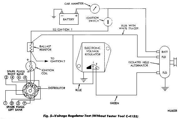
Another wirning diagram.
ok that was for the charging setup
now to find an ign conversion looking..........ok found it on fourforty site
[FONT=helvetica,arial]Troubleshooting[/FONT]
[FONT=helvetica,arial]Troubleshooting an electronic ignition system is fairly simple. Once it has been determined that there is no spark, there are a few quick checks that can be performed to determine the cause. A DC volt/ohm meter can be used to check the continuity of the pick-up coil. It can be checked at the leads as they leave the distributor, or on pins 4 and 5 of the ECU connector. When measuring the resistance across the two leads of the pick-up coil you should see a 150-900 ohm reading. Always flex the wiring leading to the distributor and to the ECU while checking the resistance to be sure that there are no breaks in the wiring. You should also check for 12 volts at pin 1 of the ECU connector when the ignition is in the "on" position. It is also important that the ECU be securely bolted in place and that bolts provide a good ground to the ECU housing. The only other lead that is connected to the ECU is the "-" lead to the coil, which can be checked to insure that it is not broken. [/FONT]
[FONT=helvetica,arial]
Chrysler Electronic Ignition [/FONT]
[FONT=helvetica,arial]The other important component of the electronic ignition system is the ballast resistor. It should be checked with an ohm meter and should have 1.2 ohms of resistance. Typically, a failure of the ballast resistor will result in the engine starting, but then dying as soon as the key is released from the start position. It is often handy to have a spare ballast resistor or ECU lying around to use for troubleshooting. [/FONT]Chrysler Electronic Ignition [/FONT]
[FONT=helvetica,arial]Upgrading or replacing an existing system[/FONT]
[FONT=helvetica,arial]When replacing a points type system, you will need the wiring harness that goes with the electronic control unit. The installation is fairly simple and the only electrical connection that needs to be made is to the ignition "+" circuit. [/FONT]
hmm I'm going to want to keep that one.. since I haven't got mine wired up yet.
hope this helps