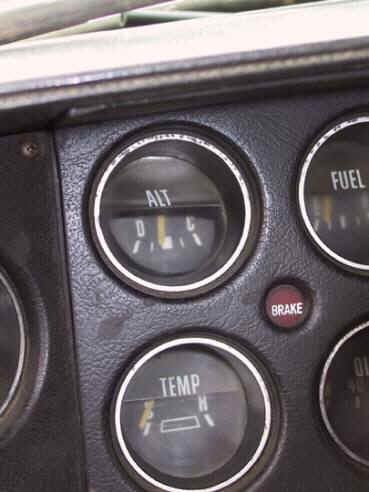
That is absolutely NOT normal, and likely will cause a battery overcharge condition. My "usual instructions" for testing is to
Either find the "switch" side of the ballast or the alternator blue field wire. Connect one lead of your meter to that, connect the other to battery POSITIVE and turn the key to "run" with engine stopped. With the meter set appropriately, you are hoping for a VERY low reading, less than .3V (3/10 of one volt) ANY drop in this circuit ADDS to the voltage regulator setpoint and raised charging voltage.
Let's say that you in fact read 1 volt in this test. With the engine running and charging, and if the VR is set properly for nominal 14V, you will have FIFTEEN volts at the battery, while in operation.
I've posted many times on this, and the most likely candidates are the primary power distribution
In "sort of" order the suspects are
Bulkhead connector, fuse link, ammeter, right at the fuse box IE the wire to the fuse clips buss, and the "welded splice."
Start by reading this article if you have not
http://www.madelectrical.com/electricaltech/amp-gauges.shtml
The example photo they show
looks EXACTLY like "several" pickups I saw in that age range where things like winches (some people call 'em wenches) or snow plow hoist had been installed
On some years, the dash construction is PLASTIC and the ammeter is a sandwich of parts held together by the tension of the stud nuts THROUGH that plastic. So if the ammeter gets a 'little warm" from high current, the plastic softens, and the connection gets EVEN WORSE which then gets downright HOT
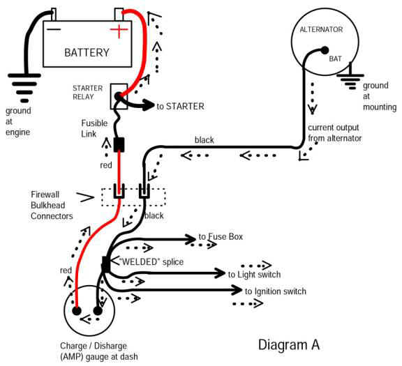
Refer to their simplified diagram on the page:
Follow the "current path" from the battery.....starter relay junction........fuse link.......bulkhead connector......ammeter......welded splice......fuse box
Each and every place named above is a possible trouble place. You must go along each path, while under load, and check what your drop is and see where you are losing power.
PLEASE read the article carefully. It contains a lot of good info. No, lol, I did not write it.
Bad bulkhead connector terminals and the ammeter are covered.
Additionally, you can have drop to the voltage regulator / ignition circuit through the ignition switch and switch connector. One "way around" this is to use the ignition "run" feed to trigger a "Bosch" style relay and feed the ignition / VR off that
WELDED SPLICE. This is rare but does and has happened. In my lifetime, I've been aware of perhaps eight of these failed. There is a splice up under the dash in the black ammeter wire. If you suspect it, you must cut open the harness for a few inches, starting at the ammeter, and find it, and inspect it. Again this is RARE. Find and fix "everything else" and keep it in mind.
FUSE PANEL. For circuits (not ignition or VR) that go through the fuse panel, keep in mind the riveted wire connections and condition / tension /rust /corrosion of the fuse clips.


