HEI in Mopar ECU casing

-

Pompis

Well-Known Member
Joined
Nov 16, 2012
Messages
229
Reaction score
22
Location
Sweden
I have wanted to do a HEI conversion for my Dart for a while. But since I dont like the look of the GM HEI and had a bad Mopar ECU lying, I came to the conclusion to combine them both after reading a post where trailbeast done the same.

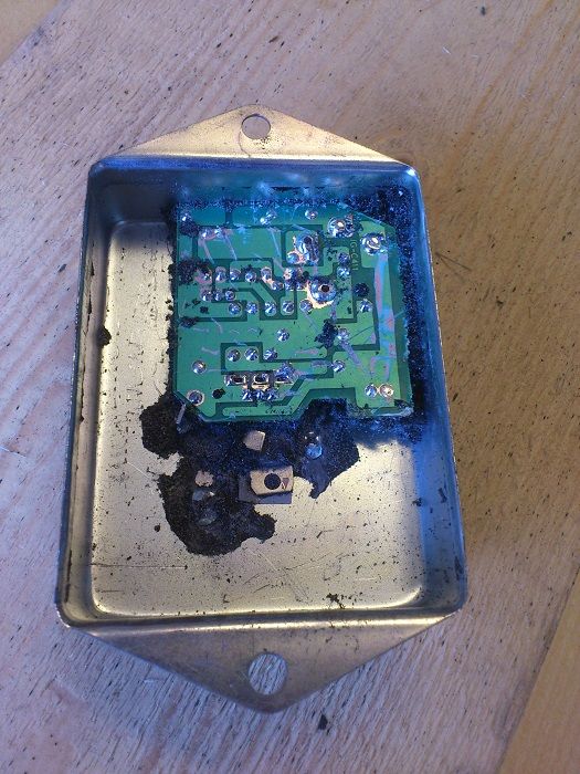
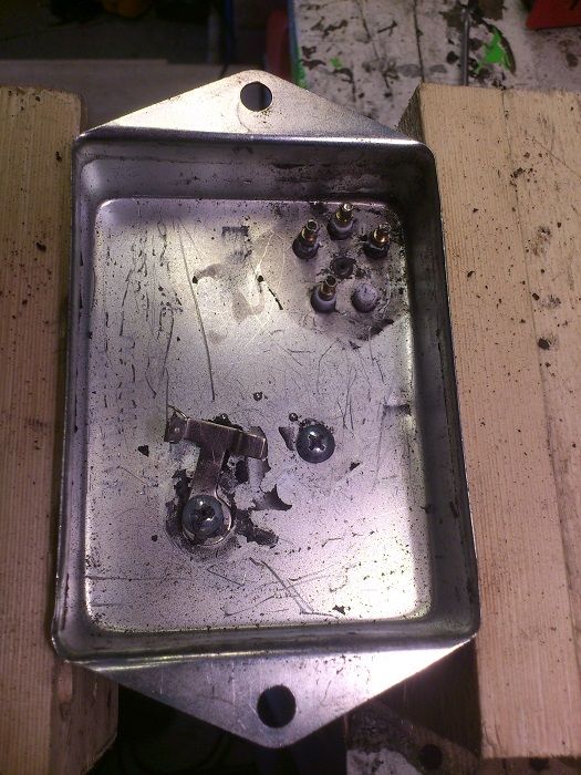
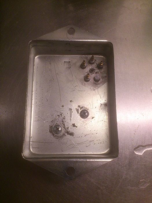
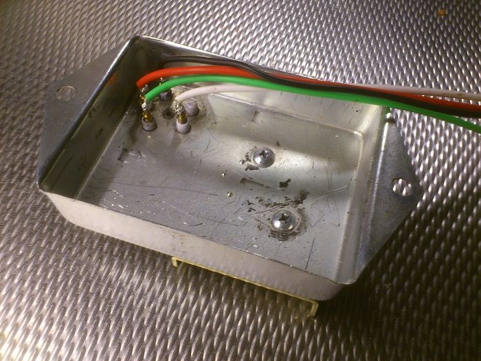
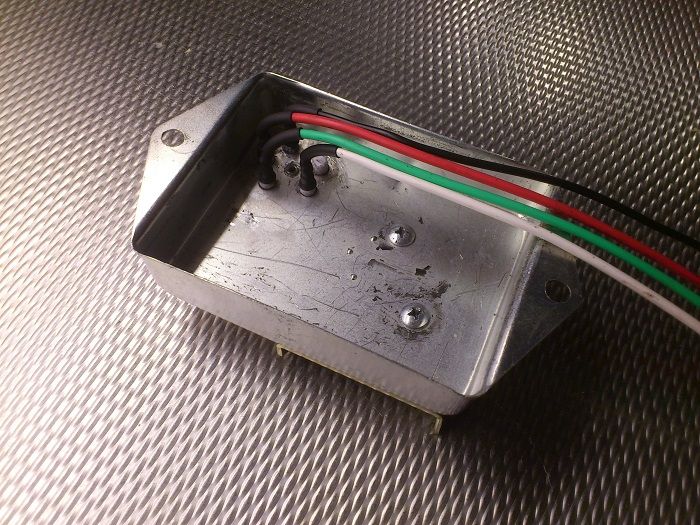
I used a heat gun and screwdriver to remove the black crap on the backside of the ECU. I cleaned the four pin holes from tin/lead. I used color matching wires to make it easy to hook up the HEI module then soldered the wires on the right pin to work with the Mopar ignition wiring. Then covered the joints with some shrink tube. Going to bypass the ballast with a wire. So if the HEI fails can I always just connect a Mopar ECU and remove the ballast bypass.

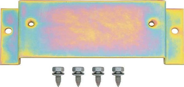
I have ordered a Pertronix D2000 HEI module. I hope this module will work great. I'm going to mount the HEI module on a bracket that I will make in aluminum that will look like the Mopar ECU mounting bracket shown in the last picture. I hope this bracket will help cooling of the HEI module and at same time goes hand in hand with stock appearence. Going to screw the ECU casing over the HEI module. I think/hope this will turn out great and look like factory. Going to use a Pertronix 45111 epoxy filled canister coil for the look too.

Will update soon. Thanks FABO
DSC_1799_zps3c123409.jpg


DSC_1800_zpsc67b7523.jpg


DSC_1801_zps493f44b5.jpg


DSC_1802_zpsef717078.jpg


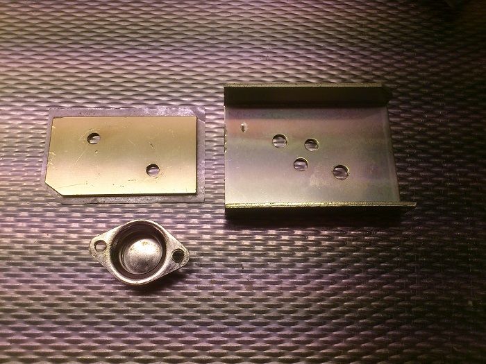
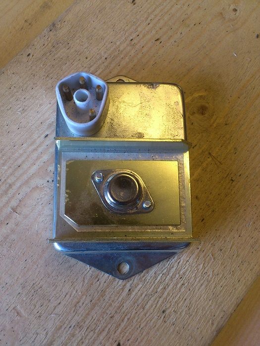
After I removed the screws to remove the ground strap or whatever it was I found out that this made in Taiwan or China ECU have a fake transistor. I guess the fake transistor is just for the look sake.
DSC_1803_zps909f715e.jpg


DSC_2012_zps42571b2c.jpg


DSC_2018_zps101b109c.jpg


DSC_2019_zps39ab0150.jpg


md4698_zpsa5022d4c.jpg
 
!!!HOLY CRAP!!! So the "transistor" and the "heat sink" on that particular box is a ????FAKE!!!!!
 
No wonder that Ching-Chang crap fails all the time.
 
Yes it's fake. If you look at the picture you see a funny thing, the heat sink have holes for a transistor but the other plate that the "transistor" is mounted on have not any holes. And the "transistor" is just a empty cap.

DSC_2021_zpsd05c6da5.jpg
 
In the 3rd picture from the top, the TO-220 tab transistor is show. It replaces the fake TO-3 package transistor. The insulating pad under the TO-220 is shifted, and may likely be the point of failure. There is approximately 400V, between the tab and case, I doubt the insulator was doing its job. The 400V transient at ignition event, may arc to case, around edge of insulator.
 
Well since he's taking it apart, this may not be a legitimate argument. That is, the "tab could be shifted" during the process of getting the guts out of the box. I just find it extremely hilarious that a manufacturer would go to the trouble of worrying about appearance of a component just so people "see what they expect"
 
Well since he's taking it apart, this may not be a legitimate argument. That is, the "tab could be shifted" during the process of getting the guts out of the box. I just find it extremely hilarious that a manufacturer would go to the trouble of worrying about appearance of a component just so people "see what they expect"


they do that more then what you would think!
 
I could be wrong, but it looks like the part is still being held by the flimsy retainer and the potting is under the insulator, so it might have been assembled like that.

What is scary is the Chinese, knock off chips that do not work. Parts are laser branded, so they look correct. They have no die inside, or a cheap die of different function. I would hate to be a buyer, trying to find the lowest cost parts today,
 
very cool and just think that gm module will live longer being away from all that heat inside the distributor lets keep this a secret Lol
 
What is scary is the Chinese, knock off chips that do not work. Parts are laser branded, so they look correct. ............ the lowest cost parts

Before he left us, my old engineer buddy told me a story of a project he worked on, by a co. that is now gone. They designed this board, and it turned out the clock was somewhat critical. "Off the shelf" clock modules were not dependably within tolerance. So they contracted --and it turns out-- with a Chinese company, again, that old "lowest dollar" to have modules selected and marked specifically.

It turns out...........that all the Chinese did........was to mark a bunch of modules. They didn't actually test and select them, they simply MARKED them and sent them back. Once these got into production, it turns out to have had about a 30% failure rate, but worse, this was "in the field" "after install," as ambient heat/ cold affected them, along with normal issues, electrical, etc.


Of course this was all done in the "vacuum" between the bigwigs, the engineers, production, etc, all insulated from each other.
 
I keep in touch with a few engineers, not much design, nor manufacturing here, the engineers now work at an international level juggling paper work. If the paper work is good, all is well :).... not really, the customer is the one that suffers.
 
Curious....can you please post a photo of the other side of the board you removed?

Thank you!
 
very cool and just think that gm module will live longer being away from all that heat inside the distributor lets keep this a secret Lol[/QUOTE

Heat yes, length no.

The GM module needs to be really close to the distributor, because of the drop thru a long wire.

Found this out on my engine start stand, I had all the wiring at the front of the engine, near where the radiator is, mounted the module at the front.
No fire. After checking all the wiring etc, and doing a little reading.

Moved the module to the back of the stand, actually bolting it on the back of the head of the motor.

Instant spark.

Keep the wiring short like under 2' from the distruibutor and you should be fine.
 
Thanks for the stories and input.:thumbup:

Sorry jos51700 I don't have any pictures on the board and I have thrown away the board. But I remember that it had a yellow capacitor and a three legged transistor.
 
Myth.
Mine are a good 24 inches long and run parallel all the way to the module.

Just sayin. :D

Twisting is about adding common mode rejection. When the wires are twisted together, what noise goes in + wire is canceled by the noise in the - wire of the pickup cable. So it is possible to be lucky and have the sensor wire more together in parallel and not intertwined enough with the coil wire. If one is more parallel with the coil wire, there can be coupling of the ~400V transient there, with the 2V pickup signal when cranking. It is a relative thing, if noise exceeds are certain margin, then no-good-worky, and some problems go unnoticed. Not many use a scope, and view the necessary waveforms.

I am old fart industrial control electronics design guy, and a bit AR. I use a twisted pair shielded cable with a ground at one end, and a separate cable for power and ground to a real ECU. However with all said, the Mopar variable reluctance distributor is not my choice. I am a Optical or Hall sensor guy, for a few good reasons.
 
The original pickup wires were never twisted either. :D

I'm just arguing with you for the fun of it Kit.
Of course I understand, and you are right.

It's just not critical or mandatory to twist the wires. (Unless of course it won't run right or start.)
And it sure couldn't hurt either.
 
I have wanted to do a HEI conversion for my Dart for a while. But since I dont like the look of the GM HEI and had a bad Mopar ECU lying, I came to the conclusion to combine them both after reading a post where trailbeast done the same.

I used a heat gun and screwdriver to remove the black crap on the backside of the ECU. I cleaned the four pin holes from tin/lead. I used color matching wires to make it easy to hook up the HEI module then soldered the wires on the right pin to work with the Mopar ignition wiring. Then covered the joints with some shrink tube. Going to bypass the ballast with a wire. So if the HEI fails can I always just connect a Mopar ECU and remove the ballast bypass.

I have ordered a Pertronix D2000 HEI module. I hope this module will work great. I'm going to mount the HEI module on a bracket that I will make in aluminum that will look like the Mopar ECU mounting bracket shown in the last picture. I hope this bracket will help cooling of the HEI module and at same time goes hand in hand with stock appearence. Going to screw the ECU casing over the HEI module. I think/hope this will turn out great and look like factory. Going to use a Pertronix 45111 epoxy filled canister coil for the look too.

Will update soon. Thanks FABO
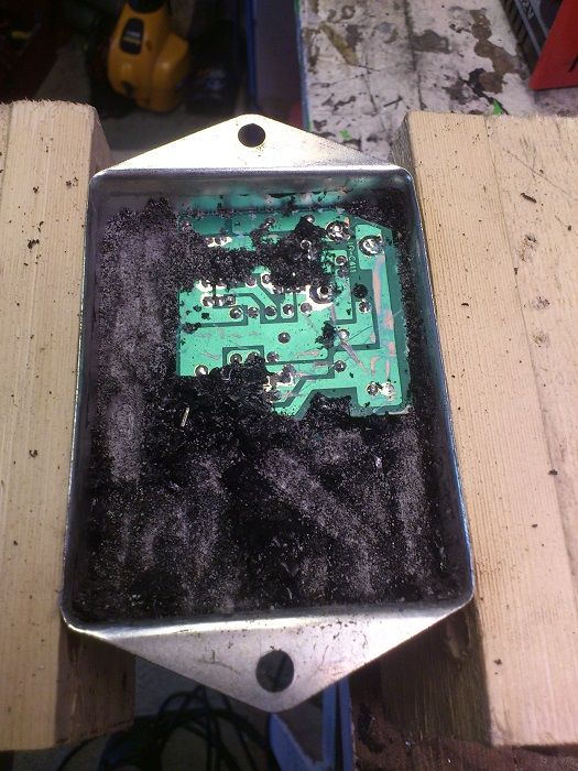
DSC_1799_zps3c123409.jpg


DSC_1800_zpsc67b7523.jpg


DSC_1801_zps493f44b5.jpg


DSC_1802_zpsef717078.jpg


After I removed the screws to remove the ground strap or whatever it was I found out that this made in Taiwan or China ECU have a fake transistor. I guess the fake transistor is just for the look sake.
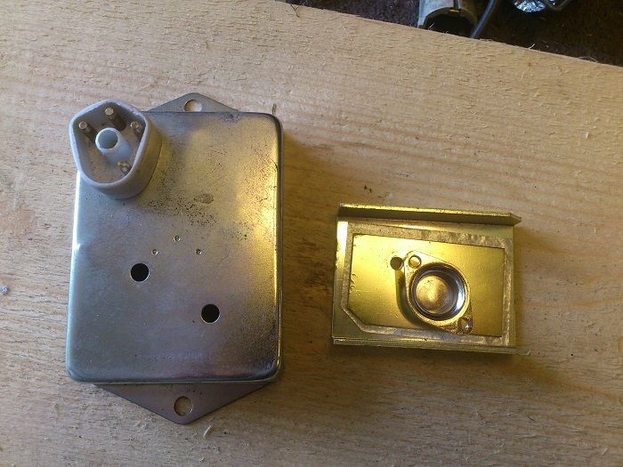
DSC_1803_zps909f715e.jpg


DSC_2012_zps42571b2c.jpg


DSC_2018_zps101b109c.jpg


DSC_2019_zps39ab0150.jpg


md4698_zpsa5022d4c.jpg


I was just thinking about this as a project last week. Glad I am not the only great mind.
 
Pompis,
Very useful info. Those Chinese are clever fakers, and are good at putting lip-stick on a pig. Somebody (273?) posted a photo of an MSD box that was empty inside, save for a little HEI module. I wonder if the Chinese sold those cheap on ebay. They even go so far as to laser engrave fake SN's.

I think your plan is a great idea for people already wired for the Mopar electronic ignition. I wonder why you are using a Pertronix module. The simple 4-pin GM HEI modules are ~$10 new and proven. Be sure you get a good ground to the case of the module and use heat transfer paste to the aluminum plate.
 
The original pickup wires were never twisted either. :D

I'm just arguing with you for the fun of it Kit.
Of course I understand, and you are right.

It's just not critical or mandatory to twist the wires. (Unless of course it won't run right or start.)
And it sure couldn't hurt either.

I know you are messing with me, and it is ok. Just because Mopar did it, does not make it correct. They were even too cheap to add an essential wired ground connection to the box. Same with voltage regulator. If you want to drive a Mopar with a mystery of performance, try a lean burn, or EFI with logic and power modules. Those are rare in running order.
 
I know you are messing with me, and it is ok. Just because Mopar did it, does not make it correct. They were even too cheap to add an essential wired ground connection to the box. Same with voltage regulator. If you want to drive a Mopar with a mystery of performance, try a lean burn, or EFI with logic and power modules. Those are rare in running order.


not so rare at all, considering the newest lean burn computers are 24 years old and alot of people over on dippy.org are still running them. Its more comman for the carburators solenoids to giveway then the computer

pretty good getting 24 years out of a piece of electronics thats mounted directly above an enormous amount of heat and vibration
 
-
Back
Top