Ignition Coil Testing

-

KitCarlson

Well-Known Member
Joined
Jan 17, 2008
Messages
2,626
Reaction score
464
Location
Middle Tennessee
When I built my electronic advance ignition, part of the plan was to evaluate ignition coils. I got side tracked when looking at RPM data logs, I discovered that my transmission was starting to slip. So I rebuilt it .... and did not get back to making an ignition coil test setup.

There have been recent posts about can coils vs E-core. Specifications provided by vendors are often poor. It is still possible to test a coil and evaluate the important coil parameters.

I recently found a Arduino Nano board for less than $10. It has an Atmel AVR ATmega328p micro controller. I am familiar with it because I first worked with a similar predecessor about 13 years ago.

I started with the code developed for the injector tester, took out features and added some. The user interface is via USB using a terminal emulator. The terminal lets me use keys to send characters to the tester, and the tester sends characters back that are displayed on the terminal. So there is no hardware like a LCD, or custom keypad.

The coil driver consists of a IGBT a couple resistors and a small transistor. The transistor and current shunt resistor serve as a current limit. The current limit is a means to eliminate a ballast resistor. It is set to about 6.5A.

The programming consists of a user interface, so the test parameters of RPM, dwell, minimum spark duration, counts and start can be controlled.

The test parameters are then used to operate an internal timer to control the coil charge, and off intervals.

There is a means to monitor the charge current, and spark discharge current using shunts and a scope. The bottom trace is the coil current, the top trace is the spark current. Spark current is negative.

The 6000 RPM test shows that the reduced dwell and short spark duration, helps build coil energy. I can write more about that if there is interrest.
 

Attachments

  • 20140405_142504.jpg
    65.8 KB · Views: 453
  • 20140405_142519.jpg
    70.2 KB · Views: 395
  • 20140405_143209.jpg
    45 KB · Views: 406
  • 20140405_143528.jpg
    20.3 KB · Views: 375
  • 20140405_145657.jpg
    50.7 KB · Views: 393
  • 20140405_145319.jpg
    21.7 KB · Views: 346
Dude, that's awesome! I built a megastim that can tickle a coil up to about 4Khz. sounds like a MIG welder. I have an EFI forum thats always looking for stuff like this to bench test components. PM me the details please!
 
now theres a cat that knows how to test stuff. so my Q is what coil to get to replace the one on my 2001 dak V6 3.9?
 
Leave it to Dave to come up with this stuff!!!
 
moe,

I would think the OEM coil on the V6 would be good enough. The OEM ECU's of often have dwell compensation for a particular coil. Deviating from that may result in undesirable performance or other problems related to EMI, or ECU damage.
 
I only have a couple hours in this project. I put some automatic features in the settings. The total period between ignition events is = dwell time + minimum spark duration + off time. The reciprocal of the period, times 15 is the engine RPM (for a V8). At low RPM there is plenty of time for dwell, and spark duration. As RPM increases the available time is less, so dwell must decrease, or there would not be time for a spark. At 6000 RPM, there is only 2.5mS time between ignition firings. The spark duration is reduced, and the coil holds the energy, and the next dwell adds to it. That is what is happening, in the stair step look of the last scope picture. The test counts was set to 8 ignition events, an actual running engine would be stable, like that after the 5th event.

The blue text in the dwell setting is automatically reduced by the program, showing the dwell is reduced to accommodate increased RPM. Same happens if min spark duration is changed.

There is much more that can be done, things like the tester measuring the coil inductance from the rate of current rise, coil resistance and supply voltage.
 

Attachments

  • untitled.pdf
    10 KB · Views: 351
This is fascinating, 'specialy for an electronincs guy like myself. So is the point to evaluate coils at higher RPM's in general, to see what is best for NA V-8's or....???
 
I'm going to HAVE to order a couple of these boards..........
 
The unit is to help me better study dwell and spark duration at higher RPM. Plug gap, and cylinder pressure plays a part, since they raise the voltage, increasing energy pulled out of coil. The tight plug gap is keeping the energy low, for safety. Monitoring of the current, and controlling the coil charge is done by modern ECU's. I may play with that some, on a more powerful platform.

This is a cheap way to make sparks, but care must be taken, or it could kill PC and make smoke. Part of this project, was to see if Del would get interested. He has, so I am in the process of documenting my work, so he and other brave souls can play too.
 
I started to search, the other day. Sometimes my hands hurt so bad, I have a friend that is interested in what is known as QRP radio. This comes from the old telegraph and radio what is known as "Q" signals, "QRP" means "shall I reduce power" and "QRP" operation has become a "gentlemans" agreement" sort of a contest of "5 watts or less" deal. In other words "how far can you get" on less and less power. And of course this means CW or morse code, because this is the lightest, simplest way to get portable equipment.

But the PROBLEM is that it hurts my fingers to operate a key, nowadays, and to operate a pencil!!!!

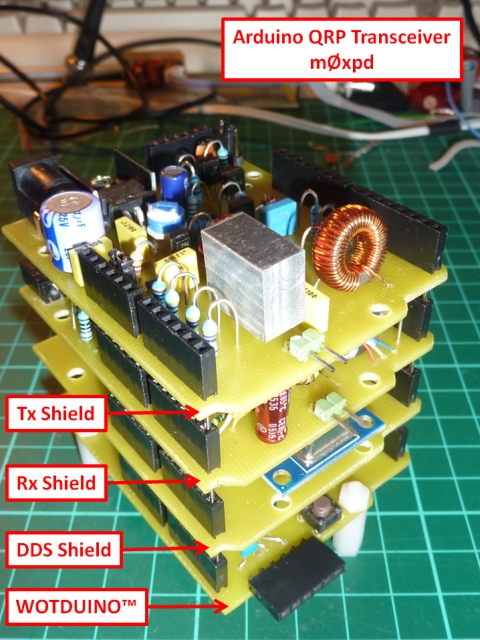
The thing is, there are more and more amateur based projects on processor based 'stuff', that is basic stamp, arduino, and rasberri pi, etc:

QRP transceiver / arduino:

http://m0xpd.blogspot.com/2013/03/arduino-qrp-transceiver.html

Stack.jpg


And Ten-Tec is in the mix, too

http://radioaficion.com/cms/ten-tec-506-rebel-arduino-qrp-transceiver/

timthumb.php
 
I think it would be fairly easy to make a keyer that you can type with a terminal or keyboard, and it would make the code. I am sure it has been done before. I can help with code if you like. There are AVR pico amp controllers, that take very little power.
 
Part of the problem is copying. I've never been able to put my brain around "copying in my head." About the best I've done all these years at my best was around 25 WPM and that was years ago. I noticed a few weeks ago I sometimes get "spacy" trying to spell. I hope to ''ell I'm not going senile. What's that other word?

Hanging onto a pencil cramps my hands, too. But regardles, I'd like to order a couple of these boards, now that they've become so darn cheap and play, a little.

I've also been meaning to order an ebay interface for USB - to CAN bus to see if I can do anything with the Holly ECU "just in case" that goes anywhere. Evidently the Holley proprietary touchscreen thingie (fer 700 bucks) runs some form of Winhozed CE, I forget which version. You can get updates for it, so maybe you could put that together with a generic CE device, don' know
 
I changed the circuit slightly after finding that pin that was used to drive the IGBT was slowed down slightly by driving the LED indicator on the board. I moved the drive to PB3, and added a 1k resistor to ground eliminate a transient, that would sometimes reset the Arduino Nano. The LED absorbed the transient, in the original connection.

I have updated the schematic. I also found it necessary to use a USB cable, with a ferrite filter, on both ends, to avoid intermittent USB communication failures. The spark is healthy now. The change does not affect the earlier current based measurements. It does change the dv/dt when the coil is released to generate the spark. I hope to find an affordable high voltage probe for my scope.
 

Attachments

  • CoilDrv.pdf
    10.7 KB · Views: 280
I changed the circuit slightly after finding that pin that was used to drive the IGBT was slowed down slightly by driving the LED indicator on the board. I moved the drive to PB3, and added a 1k resistor to ground eliminate a transient, that would sometimes reset the Arduino Nano. The LED absorbed the transient, in the original connection.

I have updated the schematic. I also found it necessary to use a USB cable, with a ferrite filter, on both ends, to avoid intermittent USB communication failures. The spark is healthy now. The change does not affect the earlier current based measurements. It does change the dv/dt when the coil is released to generate the spark. I hope to find an affordable high voltage probe for my scope.

I've got a big ole HV red probe left over from my TV repair days. It's really intimidating looking, about a foot long and something you would not want your proctologist to get ahold of.
 
Hey Dave just sent ya an email. Got off my dead A$$ and ordered a couple of boards and other junk from that outfit you sent the link to. Spent a whole 50 bucks on junk, LOL.
 
I find it easy to spend money on electronics parts. I will check my mail.

Last night I did a few minutes of work to make a low voltage sine wave with timer0, and PWM, so I can drive the coil primary, then measure the secondary, to determine the turns ratio. By doing that it is easier and safer thsn trying to measure the secondary for spark voltage. I also bought a $25 2KVscope probe for better measurements.
 
-
Back
Top