No spark and i can only get 5V at the coil.

-
Status
Not open for further replies.

SwingerLSX75

Well-Known Member
Joined
Feb 10, 2015
Messages
1,447
Reaction score
1,906
Location
Gold Bar, WA
OK guys I had this over in the slant 6 section on one of my previous help threads but figured since its an ignition/electrical issue this would be the place to put it.

Problem is I'm getting no spark anymore(after having run just fine), I initially started troubleshooting because it would randomly shutoff while idling. Then it began not starting up anymore either. I noticed there wasn't enough power coming out of the ignition so I replaced the ignition switch.

I am measuring 5.1V at the positive lead on the coil with the engine off and the key in the "on" position, and checked and reset the air gap with a brass feeler just like it said to use in the manual. From what I understand normally you will have between 7-10 volts at the positive terminal on the coil with the key in the on position. Am i right?

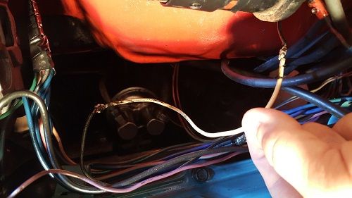
After looking through the diagram in the manual and it showing where the wires run and everything I began basically unwrapping all the electric tape that was covering the ignition system and that's where the fun began. First I found this(pay close attention to the blue wire in the middle of the picture) about 8" down the wire after it leaves the firewall connection.
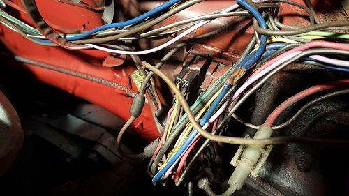
I'm not old enough to have been born when these cars were made but does that look like something a new factory car would have? I traced out the blue wires one ran to the ballast resistor, one ran up the drives side to the little vacuum thing( cant remember the name of it right now)
http://s450.photobucket.com/user/DDGDSM/media/The Dart/20150617_202121_zpsreubm3ms.jpg.html
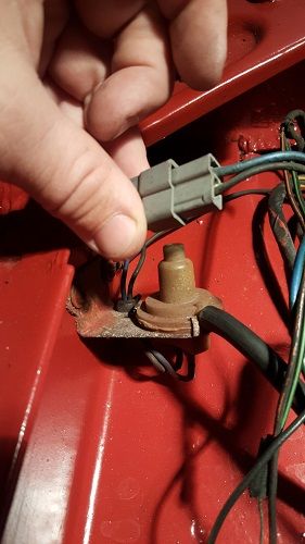
and then the other went to the passenger side where I found this, yet another splicing together of this one blue wire into 3 other blue wires. The other 3 look to lead to the 3 electronic boxes on the passenger side fender well. Yet again not something I thought id be seeing from a factory harness. So I am in full wtf mode at this point.
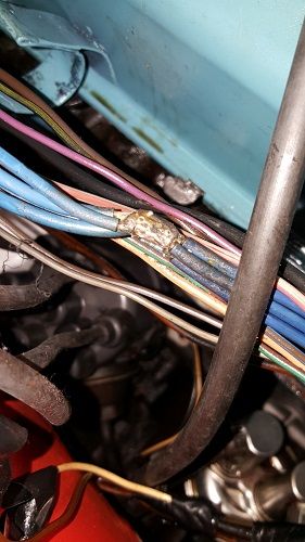

After seeing this I measured the voltage with the key in the on position and it still reads 11-12v like it should.

I went back and looked at the bottom right connection on the ballast resistor that is supposed to be the feed for the coil + terminal was a brown wire. So I traced the brown wire over to the passenger side of the bay and began peeling back the electrical tape to see if there were any issues with the brown wire. Then I fine a cluster **** after I get the tape off where it has two exposed wire sections essentially just hand twisted together and wrapped in electrical tape. Had to take a break at this point because I was a little pissed that one of the previous owners had thought this was sufficient. After cutting the wire to clean it up I noticed a considerable size difference in the two wires. So I began tracing again and it led me here
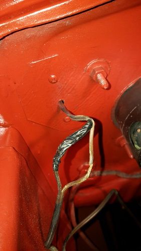

where it goes into the firewall and then comes back out and connects to the positive terminal on the coil( you could see why I was upset). Then it registered someone had the damn positive coil wire running to something inside the car and then back out to connect to the coil. So part of reason I'm not getting enough voltage to the + terminal on the coil is because they had rerouted the brown wire carrying the coil + voltage to something under the passenger side dash and then had a much smaller gauge wire come back out and connected to the coil's + terminal. It got a little late and by the time I got off the phone with the original owners of the car, it was too late for me to keep messing with it. But come to find out the original owner had installed a fuel cutoff switch under the dash on the glove box side and thought tapping into that wire for 12v power would be best.
 
Ok so just by removing that one switch and fixing the connection on that wire I went from 5V at the + terminal on the coil to 5.5V. I took a look at the negative cable leading to the coil and noticed some more electric tape and decided to remove that and found this two cut sections hand twisted together. Both within the first 8 " of wire going away from the coil "-" terminal.
http://s450.photobucket.com/user/DDGDSM/media/The Dart/20150618_153127_zpsdjoeutyl.jpg.html

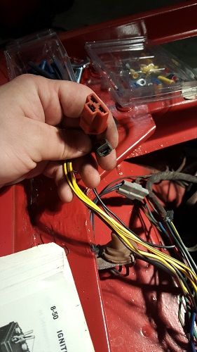
I fixed that part then I started tracing cables again and remembered a splice in the brown wire from the ballast to the coil + terminal. So I traced it out and it led me up driverside fender well to this connector which wasn't plugged into anything. Anyone have any idea what this would have went to? It was just sitting right up by the front side of the battery(the opening to the grill/headlight area).
http://s450.photobucket.com/user/DDGDSM/media/The Dart/20150618_155853_zpskheqnrzv.jpg.html

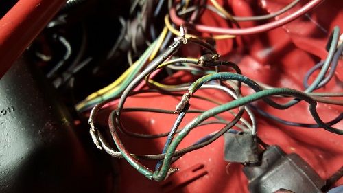
Tracing all the wires back tot he ECM I noticed some more electrical tape that looked a little too large for the wires, so I peeled it back to find this. Every wire going into the ECM had been cut and either twisted/taped/or soldered back together.
http://s450.photobucket.com/user/DDGDSM/media/The Dart/20150618_153533_zps1vcl7dcz.jpg.html

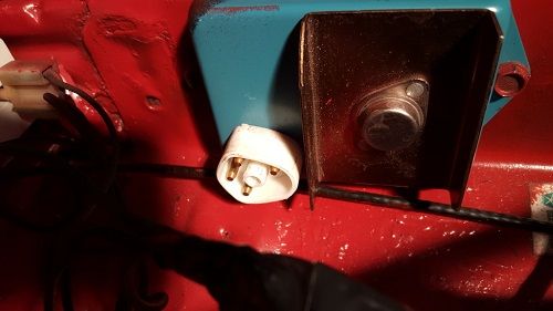
Another question I have is about the ecm and it having 5 prongs on the connector but the replacement ecm only have 4 prongs total. Is that normal or what?
http://s450.photobucket.com/user/DDGDSM/media/The Dart/20150618_154909_zpsx2cxfoqa.jpg.html

Last but not least, im trying to figure out how im dropping 5 volts across the ballast resistor. Im showing 10.5V at the side coming into the resistor but only have 6.6v leaving to go to the coil with the key in the on position and engine off. Even when actually trying to turn the key over the voltage stays at 5V or lower at the coil. What does everyone else have for drop across the resistor?
 
A resistor is going to drop the voltage. That's what it is there for.
I've got a box of used resistors and they seem to have some variance.
I'm sorry. Did I miss something?

Your ECU could be funky. I had one that was old. It would shut the car off. But I could restart it and drive on.
It finally crapped out and bingo I figured it out.
I'd worry about getting good voltage to the coil at "start" position.
If you have 10.5 to the coil at start that should do it.
You may have other issues that then can be addressed.
All replacement ECUs now have only 4 pins.
Cars used to have a dual resistor and 5 pins.
"They" moved one of those resistors to inside the ECU.
You don't need a dual anymore. The second resistor will be just along for the ride.
Plug and play.
I may get shot, but some people say the resistor isn't necessary at all with electronic ignition. (It was for the points "they" say).
But I still run a single one to be safe on the coil. Why did Chrysler put on in there then?
I don't know.
Snort.
http://www.forabodiesonly.com/mopar/showthread.php?t=318447

I can scan some factory prints in tomorrow if nobody has any links to them.
I'd be surprised if there aren't some in a sticky on here.
 
Please learn to crop and re-size your photos. 800 pixels is the default "max."

About 5V with key "in run" is about right

Some of that wiring is out and out ooogly. Here's a simplified diagram............

Ignition_System_4pin.jpg


I only posted the "4 pin" ECU wiring because that is undoubtedly what you have. WHAT IS NOT SHOWN there is the brown bypass wire, which comes from the ignition switch, through the bulkhead, and to the coil+ side of the ballast. THIS IS the same as "points" wiring and is the ONLY supply of ignition voltage with the key held to "start."

USING THE KEY and with the key in "start" you should have a minimum of 10.5V at the coil+

Below is a bit more complete diagram for the 5 pin box. For 4 pin ECU / 2 pin resistor IGNORE the "left side" of the resistor and the far left green wire. You still need the bold blue wire going to the box

attachment.php?attachmentid=1714539125&stc=1&d=1346780666.jpg
 

Attachments

  • diagram.jpg
    50.9 KB · Views: 2,616
Please learn to crop and re-size your photos. 800 pixels is the default "max."

About 5V with key "in run" is about right


Besides fixing those wire issue's the very first thing I would do is bypass that ballast resistor and see what happens.
It doesn't cost a thing and may save you a lot of time.
Can't leave it like that, but it sure will answer some things for you.
 
Besides fixing those wire issue's the very first thing I would do is bypass that ballast resistor and see what happens.
It doesn't cost a thing and may save you a lot of time.

Just for testing. Actually I would not, I would test "as is"

One easy way is to attach a clip lead direct to the coil + and run over to battery (starter relay big stud) This will "hot wire" the thing for a test. See if you have spark then
 
Just for testing. Actually I would not, I would test "as is"

One easy way is to attach a clip lead direct to the coil + and run over to battery (starter relay big stud) This will "hot wire" the thing for a test. See if you have spark then

He is testing it as is and it won't start. :D
Jump it and see what it does.
 
New development. I took the brown power wire off the + coil terminal and when it isnt con ected to the terminal it reads 10.4V. But as soon as i reconnect it to the terminal on the coil it reads 5.5V again. Any ideas? Im going to jumper it in the morning and post results.
 
New development. I took the brown power wire off the + coil terminal and when it isnt con ected to the terminal it reads 10.4V. But as soon as i reconnect it to the terminal on the coil it reads 5.5V again. Any ideas? Im going to jumper it in the morning and post results.

You are probably getting a ghost reading. Modern meters are very high impedance. EG you can set it on AC, ground one probe "in the ground" and hang onto the other with your fingers. Depending on where you are, you can read a fair amount of voltage, sometimes

The ONLY time the brown is "live" with battery voltage is with the key in "start."
 
The only time I reference voltage is with the key in the "on" posiiton(turned forward to where the oil light is on, and just before i start the car). Ill have to make a video to show you what i mean. But literally if I take the brown wire off the coil turn the key to the "on" position and measure the voltage it says 10.5volts, then I put the connector on the positive terminal on the coil it then drops to 5.5volts.
 
Try putting it under a load. Hook that wire to a 12V test lamp, see if it lights, and measure the voltage. If it does, you might have an ignition switch AFU
 
OK look, it's simple

That brown wire is SUPPOSED to only go one place......from a contact on the ignition switch, to the coil +. It should only be "hot" when the key is in start No other time.

So either the switch is mis-wired, or the switch LINKAGE is screwed up, and it's not in the right position, or the switch is AFU.

Or you are somehow makiing a mistake I cannot "see." From the looks of that wiring, it's been pretty well hacked up. I cannot tell you much more

Have you tried jumpering a wire with 12V right to the coil +
 
This issue was present with the old ignition switch and the new one. The brown wire i have goes from the ballast on the fire wall to the + on the coil, however it also has a spliced in line that runs to the connector you see in my hand in the picture above (which isnt connected to anything. I will be removing the splice tomorrow and trying the 12v jumper from the battery to the + on the coil and ill post the results.
 
"The brown wire i have goes from the ballast on the fire wall to the + on the coil" The confusion here is that the brown wire that you are looking at appears to be the wire from the low voltage side of the ballast to the coil +. The brown wire that everyone is thinking of is from the IGN2 position of the key switch to either of those 2 points (usually the low voltage side of the ballast) via the firewall connector.

I think you DO have the wiring diagram in the FSM. Follow that to see if you can ID that 3 prong connector; I suspect your wiring is all hacked and cross-connected so with us not there physically, it is going to take a lot of description on your part for anyone on this end to figure out what has been hacked or crossed.

It would be very helpful to start posting more data with each report, under the same set of conditions. Keep the - lead of the meter at the - lead of the battery at all times so that is a constant reference point. Measurements from more points is needed to find if there is a significant voltage drop and how much. Just reading at one point is not enough.

If you can, please post the voltages at:
- battery +
- input and output from ignition switch
- blue wire to ballast
- wire from ballast to coil +

BTW, did you ever run the spark test that I described over in the /6 section? That would have separated the coil and ballast from the ECU and distributor to help you narrow down the problem area.

BTW#2: Does this car's car have an electric choke? I asks as that could be one of the extra blue wires spliced in. That will load the ignition switch and cause extra voltage drop in the IGN 1 (blue wire) circuit. I would sure like to know to what parts those extra blue wires go to. One is likely the voltage regulator: flat box on the firewall with 2 leads, one blue and one green. Another blue wire should go to the blue field wire on the alternator.

BTW#3 One more thing to check: Make sure the brown wire from ballast to coil + connects to the low resistance side of the ballast. There is a low resistance side (about .6 ohms cold) and a high resistance side (about 5 ohms cold). If your brown wire is connected to the high resistance side, then it will drop the coil+ voltage way too much. And besides, if you have the later ECU wiht 4 prongs, you don't need the high resistance half anyway. In that case, you can just convert to a single ballast with the correct cold resistance.

Can you take a pix of the 3 boxes on the passenger side to which these blue wire go?

I am suspecting more an more that a PO spliced several +12v loads in the engine compartment to the IGN1 circuit and that is overloading the IGN (blue wire) position of the switch.

Also, this IGN1 (blue wire) lead in the 1975 models goes via a fuse to the instrument cluster inside the passenger compartment via a fuse. Not what it powers in the cluster, but find the single fuse with blue wires in and out and pull it and see if that helps your voltage out to the ballast.

Have you considered another engine compartment harness? There is so much hacking in the present one....
 
The ONLY time the brown is "live" with battery voltage is with the key in "start."
Key words are "BATTERY VOLTAGE". You will still get a reading of reduced voltage in run coming from the coil terminal. Just in case that wasn't completely obvious.
 
People want to help.
I done figured "someone" would post the diagrams.
A picture is worth a thousand words.
Your car has had God knows what done to it and can drive everyone nuts.
You first.
Like the man says, it's simple
The wiring is simple.
But theory is something else. But then again he knows juicetricity.
Trying to figure out what is happening can be overwhelming if the poor guy doesn't understand the theory.
Make it look like his prints and go from there.
Unfortunately, you may have some extra "work" to do that.
But you will know what you have done the road.
My best "advice" and worth what you pay for it.
 
I asked you earlier. PLEASE resize your photos. If you don't know how say so and we can step you through that.


It makes this thread INCREDIBLY difficult to read

Also what are you working on. What year? Ya. It DOES make a difference
 
I assumed he was working on a 75 from the name and picture.
I offered to upload some prints.
These are from the 73 manual. I can only assume there weren't any big changes under the hood and dash.
I'll upload just what he should need right now so it won't make the thread too long.
 

Attachments

  • Scan1 (Large).jpg
    91.6 KB · Views: 716
  • Scan10001 (Large).jpg
    90.4 KB · Views: 719
  • Scan10003 (Large).jpg
    90.6 KB · Views: 770
  • Scan10008 (Large).jpg
    79.4 KB · Views: 683
Have you tried a different coil? Is it possible this one has an internal short and is drawing current / voltage?
 
Have you tried a different coil? Is it possible this one has an internal short and is drawing current / voltage?

See my link above for my recent sad tale of woe.
That's one thing I'm on the way out the door to do right now if I can get motivated to leave my air-conditioned house.
Try some different used coils and see if mine is sucking too much current and causing a voltage drop at "start".
Probably not. But you never know on these old things.
I freaking hate summer. Wasp, heat, humidity, snakes, UV damage.
Have I left anything out Texas?
Youse guys in the Pacific Northwest have my envy.
 
I just resized the pictures, sorry I didn't know about the size issue.

I tried the jumper from the battery to the + on the coil and it still didn't fire up, it just spins and spins.

I have tried different coils and there was no luck with either. The one installed is only 3 months old and its one of the chrome accel ones from advance.

Here are the two diagrams I downloaded to accompany the ones I have in the manuals.

UPDATE: I just realized the electrical diagrams were in the body service manual instead of the chassis service manual so im looking at those now.
diaghram2_zpsnfvdkixj.jpg
diaghram1_zpsm7g6oiyz.jpg
 
UPDATE: I just realized the electrical diagrams were in the body service manual instead of the chassis service manual so im looking at those now.

Thank you VERY much for resizing. No the main diagrams are not in the body manual. Those are only partial diagrams for stuff like tail light harness etc

OK let's make some tests. Think of the ignition as "it's own little world." Let's do some tests without the car. In other words, you should be able to "in imagination" lay the ignition out on a bench and test it.

First, some basics.

Inspect the cap and rotor, look for dirt, moisture, debri, and spark "punch through" or so called "carbon tracking."

Take your ohmmeter and check continuity (for now) of the coil wire. Shake it around.

UNHOOK anything on the coil EXCEPT the power wire from the ballast to the POS and the ECU wire from the ECU

Unhook any radio caps, or tachometer.

Work and wiggle all connectors. Work them in out several times, inspect visually with a flashlight. "Working" them will scrub corrosion off terminals, and give you a chance to feel how tight they are. Pay particular attention to the distributor connector.

Measure resistance of the distributor pickup carefully. Make sure you have good tight connections.

Then switch your meter to low AC --that's right AC volts-- and connect to the distributor connector. Cranking the engine should give you about 1V AC

Inspect the inside of the distributor. Wiggle the shaft, look for play, look for debri, rust, strike damage. If possible, get a brass feeler (O'Really's) and check the gap at .008 inches

Now, "rig" a spark test gap. Best to buy a parts store test gap. Several brands. "Rig" your clip lead to the coil POSITIVE

Take the harness connector that fits the distributor, "vehicle" end. Ground the bare terminal. This should produce ONE spark "snap" each time you ground it.

Check coil pos and neg. volts. POS with your clip lead should be 12V "same as battery." NEG side of coil should be LOW, perhaps 1V or so, less than 2V. IF IT IS HIGHER the ECU is not grounded or it is bad

(Make SURE the ECU is grounded. Scrape around the mounting, use start lock washers to remount tight)

Try cranking and see if you get sparks out of the coil with your test gap or a test spark plug
 
You do know that if you are using a 1975 Factory Service Manual, as it appears you are, then it has procedures to test every single aspect of the ignition system. ECU, ballast, pick-up module in the distributor, ignition coil itself. All of it. That's what the techs originally used at the dealership.

Have you VERIFIED there is no spark at the plugs? That means remove one, lay it against a ground and then crank the engine over. You could have something as simple as a corroded terminal in the cap or a broken coil wire.

Accel coils are junk. You can get the correct replacement ignition coil for about $19 in stock at pretty much any Autozone on the planet. Ignore the drama about the "ECU might have a ballast in it blah blah". Whether it does or not Mopar spec'd what ballast and what coil to use so put it back stock.

I think i mentioned this in another thread you started but the ballast supplies two separate voltages at two separate times:

Cranking voltage which is supplied to the coil when the key is in START. That's full 12V to help the engine start faster.

Running voltage which is resisted down to about 6-7V at the coil. That's because the coil tends to overheat and fail at full voltage. That voltage is supplied when the key is in ON position.

That's why when the run side of the ballast fails, since it does all the work, the engine starts as long as the key is in START and sending that full 12v to the coil.

Here's a challenge:

Imagine it's 1979 and you are a newer line tech at FABO Chrysler-Plymouth, and you just had a 4yo '75 Dart come in with a no-start. It's assigned to you to repair. The customer needs their car back as soon as possible because it's their only car.

Every hour you spend working on that car not only charges the customer the hourly labor rate, but keeps you from taking on other jobs. Not only that, but the customer is on the hook for any replacement parts since that car is now out of warranty.

So, what do you do? Do you take guesses and try different parts, all of which are billed to the customer. Do you fart around wasting diagnostic time?

Or do you utilize the tools at hand, namely the proper electrical test equipment( a spark tester and an electrical meter) plus the FSM with it's detailed diagnostic instructions to quickly isolate the real problem, repair it and get the car back to the customer without excessive labor and part costs, which they would most certainly balk at paying?

:)
 
You do know that if you are using a 1975 Factory Service Manual, as it appears you are, then it has procedures to test every single aspect of the ignition system. ECU, ballast, pick-up module in the distributor, ignition coil itself. All of it. That's what the techs originally used at the dealership.

Perhaps you can post those procedures?

I have 73 and earlier, and a 76. About all they "say" is to plug in special tester Chrysler part no blishy bloshy. (Actually it's C-4166-A or C-4166 and C-4166-1)
 
Status
Not open for further replies.
-
Back
Top