NSS / backup lights question

-
Joined
Dec 3, 2011
Messages
149
Reaction score
1
Location
Honolulu
I have a 1965 Plymouth Valiant (auto, column shift) that has a 1971 Dodge Dart 904 trans. Although it was originally a column shifter I have it hooked up via cable on a B&M floor shifter.

I'm in the process of wiring up my NSS and reverse lights. I want to make sure I have this right:

- the later 904 has a 3 prong NSS, the two outside prongs wire up to the backup light (purple wire), and the middle wire connects to the ground on the starter relay. when the car is running, how does the battery feed power to the backup lights when in reverse? is it via the starter relay ground?

- the 1965 backup light wiring is a single purple wire that runs to the back. originally, it was plugged into a socket on the steering column. i'm planning to combine the two outside wires on the NSS into the one purple wire that runs to the back, is that correct?

- also, there's a white wire bundled up with the purple wire that connects to the same socket on the steerer tube. what is the purpose of this wire? the other end connects to something on the dash. i just want to make sure all wires are accounted for and i'm not disconnecting anything important.

thanks in advance for your help! :)
 
how does the wiper switch work, i didn't feel any other wires coming out of it? forgive my noobness, i guess i just don't really understand how the electrical system works. but i'd like to learn.
 
The wiper switch gets power through the accessory terminal of the ignition switch. On the wiring diagram from the 65 FSM the power wire (pink) is designated as V1. The wires going to the wiper motor are labeled V3, V4, V5 and V6 (for the variable speed (for the single speed they are V3 and V6). The wire going to the backup switch (either on the steering column or shifter is B1 - that's the white one. The last wire (if equipped) is the V10 (tan) which goes to through the bulhead connector to the washer pump. Here's part of the under dash harness which shows the wiper switch. Hope this helps.
 

Attachments

  • wirin diagram 001.jpg
    135.8 KB · Views: 419
i have a service manual for 65.

my problem, i think, is that i don't really understand how the electrical system works, or how to properly interpret the diagrams.

also throw parts in from different years and it leaves me even more confused.

anyway, i'm reading up on some fundamentals.
 
You are correct that the 2 outer wires on the NSS are for the backup lights. They do not get power from the starter relay, or interact with it in any way other than run close to it since the middle wire of the NSS does go to the starter relay.

The wiper wires do not go thru the bulkhead connector since your wiper motor is in the cabin (66+ have it in the engine bay). There are many wiper variations. Simplest is a single speed (I think), with just 2 wires to the wiper motor (power & park) w/ gnd return thru the body. One confusing thing is that they used the wiper as a convenient wiring junction, with wires that attach there but have nothing to do with the wiper switch itself.

It sounds right that you should locate the 2 backup lamp wires that went to the column and connect those to the NSS. Polarity shouldn't matter.

To read the electrical diagrams, just put your finger on a wire and trace it. If they cross without a dot, there is no connection there. These diagrams are very simple to read, compared with say my 85 Mercedes. You can download easier ones here, with different colored wires to make reading easier, and some that isolate the wires for particular functions, like say just the battery charging system.

Perhaps the more confusing thing is that the diagrams just detail the connections, not the theory of operation nor how the components work. For example, you see the IGN1 & IGN2 wires coming out of the "ignition switch". IGN2 can apply 12 V downstream of the ballast resistor (thus bypassing it). The diagram doesn't tell you that IGN2 gets power only with the switch held in the "start" position. Even if you figure that out, you would think that IGN1 which is for the "run" position would also get power in "start", but it doesn't. You have to test that with a multimeter or read here. Actually, my M-B diagrams are a little better since they show the internal detail of each component and you might figure how the switch works if you can interpret the cryptic symbols.
 
I think the other thing that's confusing me is how the lights will get power.

The way I'm seeing it is that I have a single purple wire going to the driver side backup light, and a second single purple wire splitting off and going to the passenger side. If I plug the NSS harness into the trans, and run the two outer wires into the single purple wire going to the back, exactly what is powering the lights?

Likewise, if the white wire is coming from the wiper switch on the dash, should it go back into the socket on the column? I couldn't see or feel any wires coming from the socket (or on the column on the motor side). So what's applying power to the switch for it to work?

Maybe I'm missing something here.
 
i have a service manual for 65.

my problem, i think, is that i don't really understand how the electrical system works, or how to properly interpret the diagrams.

also throw parts in from different years and it leaves me even more confused.

anyway, i'm reading up on some fundamentals.

I do agree that some of the interconnect stuff can be confusing. The Mopar wiper systems through the years are generally very poorly explained.

But if you can post specific questions, we can waltz you through things most of the time.
 
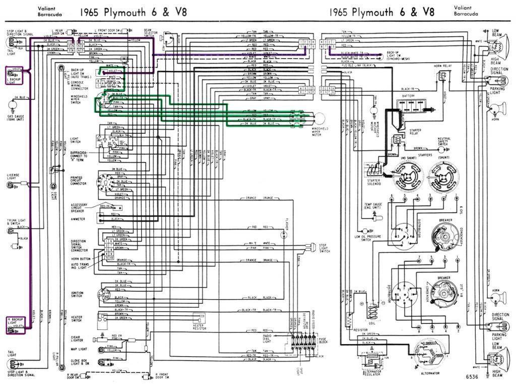
I tried tracing the connections for the reverse lights and the wiper switches on both diagrams for 1965 and 1971, since I'm trying to make the two compatible.


I still can't really see where the power feeds in. I've highlighted the wiper stuff in green and the reverse in purple. Am I doing this right?

(Sorry for the size of the pics. I like to be able to read the labels.)
 
You should remove the '71 diagram. Not only is it different from your 65, it REALLY screwed up the display. What 65Dartman posted earlier is essentially correct............


This now should be wired (in the 65) more like a 4 speed switch........coming through the bulkhead.

Hang on, I'll see if I can post some of the diagram................

65 factory manual........

[ame="https://www.dropbox.com/s/upks33txhbe9tjw/1965%20Plymouth%20Service%20Manual.pdf"]https://www.dropbox.com/s/upks33txhbe9tjw/1965%20Plymouth%20Service%20Manual.pdf[/ame]

The engine bay wiring is page 8-109. Find the "back up lamp switch" at far right middle of page, wire B1 and B2 go from the switch back to the bulkhead connector, position 6 and 7 These are both shown (chart to the right) as black with white tracer. These of course you would have to have added for the new style automatic switch.

Now go to page 8-96, the inst. panel wiring. Wire B2 comes in from position 6 of the bulkhead connector, goes down, off the page and continues on the page below. On page 8-97 B2 comes back on the page at the very bottom, goes over and connects to the kick panel connector and feeds on back to the rear lamps. The switch shown there of course is your original automatic switch on the column. If you go to the color chart at top left of 8-96, you see that "B2" is violet.

Now, we go to position 7 of the bulkhead, page 8-96, and wire B1 (B1, B2, by the way are shown dotted because these only exist in factory form for stick cars) so follow that off the page, down to the bottom of page 8-97 and you find it goes to terminal "B" of the wiper switch. Now these vary some over the years but generally, "B" is going to be a brass strap which jumpers over to V1 on the switch, possibly with a circuit breaker there on the switch. Now follow V1 up, off the page, and find it again at far right, middle of page 8-96, and you'll find it JUNCTIONS with the flasher and other wiring. Follow from that junction "Q2A" up the page and you'll find it goes to the fuse panel


Here's the 65 diagrams from MyMopar.............and I see they really don't document the 4 speed switch........

http://www.mymopar.com/downloads/1965/65ValiantBarracudaA.jpg

http://www.mymopar.com/downloads/1965/65ValiantBarracudaB.jpg
 

Attachments

  • Backup1.jpg
    33 KB · Views: 392
  • backup2.jpg
    46.4 KB · Views: 352
  • backup3.jpg
    30.4 KB · Views: 333
  • backup4.jpg
    79.7 KB · Views: 390
Thanks man, I appreciate your time in this. It's making a little more sense now as I read your explanation and the wiring diagram in my Service Manual. I'm hoping I can take a second look tomorrow on the car and see what the deal is.
 
I'll answer your specific questions about the 65 diagram you posted, which should help with the concepts.
If I plug the NSS harness into the trans, and run the two outer wires into the single purple wire going to the back, exactly what is powering the lights?
Only the purple wire from the NSS feeds the rear backup lights (why they used purple). The other white wire is the incoming +12 V supply lead. Doesn't matter which outer terminal is which on the NSS, but best to try to keep it like the factory did.
Likewise, if the white wire is coming from the wiper switch on the dash, should it go back into the socket on the column?
What is confusing is why the wiper switch is involved. Like I said, the designers often used the wiper switch as a convenient terminal tap. If you look at the wiper switch, I think you will see the two "B" terminals are directly connected, ("B" = "Battery", but not exactly). That means the white wire is always connected to the incoming pink wire (wiper switch uses also), which connects to the black "accessory bus" from the ACC terminal on the key switch. That terminal gets power in "ACC", "RUN", and "START" key positions, as I recall.
 
ok so i've been rereading the posts and trying to decipher both explanations.

white wire = 12 v incoming (also read 12v on the white wire on ignition w/ voltmeter)
purple wire = sends voltage to the backup lights

the way i'm interpreting it is,

white wire is connected to one outer prong of the NSS, and the purple outgoing wire connects to the other outer prong. (haven't connected middle prong for the NSS to the starter relay ground yet.)

lights still don't go on when in reverse.

maybe i should test my lights (new bulbs, reconditioned sockets). so i connected the white and purple via a test wire, figuring that with just the ignition on, the 12v should turn on the lights. still no go.

am i doing this correctly? any thoughts?
 
Just jumper the two outer switch connectors with key on and lamps should work. If they do, it's a switch/ transmission problem. The transmission MUST be a 69/ later transmission or the internal "rooster comb" won't operate the switch.

Power comes to the white, through the switch, and the purple routes power back to the lamps.
 
essentially that's what i did... i crossed the white and the purple wire, which should've brought the lights on. but it didn't work.

question: the bulbs only have a single wire going in, but do they work by grounding the sides of the bulb to the car body? i put some silicone anti seize on the socket so i wouldn't have any problems taking them out but now that i think of it, i wonder if that's preventing the current from grounding.
 
Not familiar with how those lamps/ sockets are mounted. Could easily be a ground problem. Look this IS electrical 101. Use your head...........do you have power at the sockets?

How to find out? Easy. Key on, in reverse, or with NSS jumpered, pull one bulb and stick your test lamp in the socket.

Is the socket grounded? Easy. Find a good ground, like up in the trunk, away from "underneath rust." clip your multimeter to that, and double check the meter by "stabbing" the remaining probe into an adjacent piece of body metal.

With the meter on "low" ohms, stab your probe at the lamp socket shell. should see continuity, very low ohms

Other ways:

With bulbs installed and powered up, hook a clip lead to a good ground and touch to the lamp shell. Do the lamps come on?

Or clip your test lamp ground clip to a good ground. With power on, stab your test lamp on the reverse lamp shells. Does the lamp light, even dim? If so, you have a ground problem there at the socket.
 
YESSSSSSSSSSSSS!!!

Got both lights to light up. The problem, was, indeed that both sockets were not grounding properly. Cleaned off the silicone grease. And then tested everything by process of elimination:

- tested the bulbs to make sure they worked
- made sure the purple wire going to the back had a solid 12v
- tested the sockets to see if grounding it to the body turned on the lights.

one light came on but had trouble with the other socket. took a dremel to the socket to clean off some of the surface rust, and when that still didn't work, took my channel locks and very slightly crimped the socket to make a better connection with the pins on the side of the bulb. and voila! it turned on!

i think next step is to hook it up via the NSS, and then test the reverse gear, but at least i know everything from the purple wire to the back works now. i will post an update later! :)
 
Cool, ya learned a little. Worst case of "not grounding" was years and years ago, "us guys" used to use landing lights. Local guy came in with old Ford pickup, had them installed in housings, mounted to front bumper. Bumper on those old Ford pickups were bolted directly to pickup frame!!!! Lights were grounding to bumper!!!!..........but bumper bolts were rusty and bumper was not grounding to frame!!!!

"He was a logger." "I'll just weld that SOB bumper to the frame!!!"
 
Wired up the purple and white to the Backup Light Switch and the ground on the starter relay to the NSS. Fired up the car and everything worked like a charm.

Not learned a little — learned a lot. I didn't remember a whole helluva lot from high school electronics but this was a good refresher. I also learned which connectors work the best when installing these kinds of things.

Thank you all for your help. I know I'm a slow learner but your guidance combined with seeing what's actually connected to what helped me big time. Thanks once again, so grateful for this forum. :) One step closer to getting the beast back on the road. :) :)
 
-
Back
Top