Wires throught fire wall

-

1973dusterkid

Watch This
Joined
Jul 17, 2011
Messages
2,270
Reaction score
68
Location
Buford Georgia
Are all the wires that run throught the firewall (bulkhead connecter) are all the wires fusable links.This is a 73 duster.
 
Absolutely not. I don't have a factory wiring diagram for a 73/4, but it's very possible there is only ONE

Not only that, but some of the circuits through the bulkhead are NOT fused in ANY way relative to the wire size. That is, the wiring will burn up before the main fuse link fries

Offhand, at least three I can think of is the "igntion run", (dark blue), the crank/ start (yellow) and the ballast bypass circuit, (brown)

Also unfused and NOT protected by a fuse link is the alternator output, which means that if a short should happen in such a way that the engine should remain running and the charging system working, there is NO protection on the main charging line.

A quick look at your FACTORY shop manual will show that

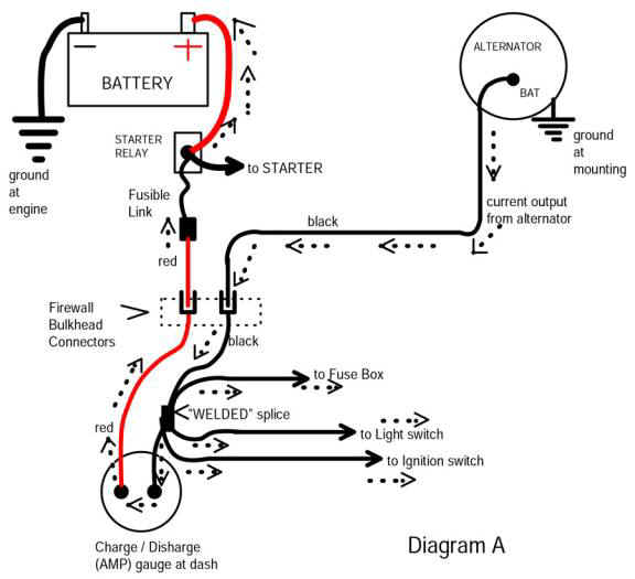
Here's an article about Mopar bulkhead connector and ammeter circuits. Scroll down the page to the simplified diagram

This article,
http://www.madelectrical.com/electricaltech/amp-gauges.shtml

Which came from here:

http://www.madelectrical.com/electrical-tech.shtml

The diagram

Notice there is ONE fuse link, which is out between your start relay "big stud" and the bulkhead. This is the "main battery feed." Notice that the BLACK main charging line comes in from the alternator, and notice the "welded splice" in the black line. This is a big welded factory harness, taped up in the main under-dash harness. IT branches off to feed the headlight switch (which has a breaker in the switch), the "hot" buss in the fuse panel, the ignition switch, and a couple of other things

NOTHING which goes to OR COMES FROM the IGN switch is fused

The IGN switch feeds:

The switched accessory buss in the fuse panel

The ignition "run" circuit (dark blue)

the yellow "crank" circuit to the start relay

the brown "bypass" circuit to the ballast resistor

NONE of these are fused

amp-ga18.jpg
 
Well I cant find a replcement bulkhead connecter so I was going to make a fuse block that I could run the wires throught and I was needing to no what wires had fuseable links.

So far I have had only one fuseable link blow and I replaced in with a inline fuse.And when it blows The car will not turn over so it is a ingtion wire.
 
No, it's not an "ignition wire."

If you read carefully what I posted, and look at the MAD diagram, the fuse link kills ALL power to the interior of the car.

One way around this is to just feed wires through the Bulkhead connector after you remove the old terminals, and ream out the two holes or so for the larger wires.

I "sort of" did this on my 67. I bought a "almost new" Painless?? wire harness that someone started to wire, some of the dash cluster wires were cut short. Mounted the fuse panel on the firewall right to the left of the heater and above the throttle pedal, and ran the wiring through the bulkhead connector as described.

I also converted my ammeter to a voltmeter as in this thread (not my invention)

http://www.forabodiesonly.com/mopar/showthread.php?t=119480

and I used a relay box out of a junker Caravan? Voyager? which I mounted under the hood, and then had relays for ignition/ headlights/ pump/ security/ etc and extra fuses for same

image.php


I have the wire manual for the car but I cant read the wire digrams
 
Reading the wiring diagrams just takes practice. Put your finger on a line and follow it. If it reaches a junction with other wires, consider all those wires the same "point" in the circuit. They are all at the same voltage. These cars have very easy to read diagrams. Try reading one in a modern car, or even my 80's Mercedes. A table to the right lists the color and gage of each wire. A smaller gage number is a thicker wire.

The bulkhead connector is not as complicated as it looks. I recall your 1973 has 3 connectors. One is the engine harness, one is for lights and horn, and one is just for the windshield wiper. Find them in the diagram by the different bumps that "key" the plugs to the connector. The contacts get corroded and cause endless problems. Not hard to fix, but most people ignore it until constant problems, then they ditch the car.
 
What do you have for diagrams? The factory shop manual diagrams are more complete, but sometimes a little more difficult to follow than the ones at MyMopar, which are sometimes incomplete as well as somewhat incorrect

If you can post sections of what you don't understand, we can walk you through it.

If you know how to "take a screenshot," that's the way I do it. I simply open my shop manual I want (pdf) and position what I want, then take a screenshot.

Save the shot to your desktop, then open it with a photo editor (I use GIMP) and crop, size, etc, then post it here.

Here's a random example of one I posted, a crop right out of the 67 shop manual

So let's take this diagram and look at a little part of it. Let's just say you were working on part of the dome/ courtesy lamp circuit. Look to the right of the ignition coil where it says "to right automatic door switch." This would be the dome light switch in the door. Follow that wire straight down and notice that it says "M2A018Y"

"M2A" is the wire number (not on the wire just on the diagram) for that section of wire, 18 is the wire size, and "Y" is for the color yellow.

It goes down to anther connector and branches off and continues on M2-18Y to the left, and down to the 6 position rectanglular connector, at the top left hole in the connector.

HERE IS WHERE you must pay a little attention. That connector mates with the other half to the left, but it is "backwards" IE a mirror image. Look at the TOP RIGHT hole, and follow those wires down to the "console courtesy lamps" and notice that now they are "M2C-18Y" and "M2D-18Y"

The other wire at the lamps, the "P" (purple) wire is not shown completely here, but it is the power source. So when the door switch grounds (door open) it completes the circuit via the "M2" series "Y" (yellow) wires.

Hope that gives you some idea. I had no professor, no school, to teach me how to read mopar diagrams, which are different from Ferd or GM. I used to maintain RADAR, later on, HVAC, and those two fields tend to draw diagrams COMPLETELY differently, and those two fields tend to be completely different from the automotive industry

For a few years I helped build, configure, and maintain a couple of Motorola systems known as "Centracom" (radio / com controller console) and "Centralink" (phone system.) One man cannot carry the complete set of manuals for those two systems!!!!

In other words, you just have to study it some.


2lk9qac.jpg
 
Ditto 67Dart273. These old Mopar wiring diagrams were drawn by hand, so they were made pretty intuitive and easy to understand. They are fairly pictoral, i.e. each component looks almost like real-life. They are also mostly on one page.

Starting in the 1980's, manufacturer's started using computer programs to drawn the diagrams, and vehicles started getting much more wiring. The diagrams now span multiple pages, so it is hard to follow a wire. Current diagrams are more like an input/output table, and not very pictoral. Still, one can get thru those, especially if you have cut your teeth on 60's car wiring. I am an engineer, but they teach almost nothing of this in college. In industry, wiring diagrams are usually drawn by non-engineers, say an english major who couldn't get another job, so don't feel intimidated.
 
The small details can cause much grief to the novice. Case in point...
Round harness connector at the instrument panel. That connector is keyed ( most are ) so they can go on only one way. The key in this round connector is commonly at the 12 o'clock position in the physical sense.
The ink and paper rendition of this connector may have the key rotated to another position ( 9 o'clock for example ). The positions of the drawn wires are also rotated accordingly so they remain relative to that key.
"It's 5 o'clock somewhere" ? Yep, where beer was used to put out the fire. LOL
Hope this helps
 
Well if theres only one fuseable link running thrught the firewall I will be able to find out ablut the rest.

Another thing that should help A LOT in that area (after you get a proper shop manual) is to print out the diagram of the bulkhead connector which are normally designated with letters, not numbers. If you print this out nice and big, you can make notes as to which wires, and as you check them off, etc.

Three tools that are a MUST have are a good 12V test lamp, a decent digital multimeter, and a bag or two of Radio Sh## clip leads. The whole mess can be found for less than 50 bucks.

Thinking about getting that testlight/test proble tool I saw on gears.
 
Can you post a link, brand, model? You may be overspending. There's no reason to spend much on a 12V lamp.
 
I got several multimeters free at Harbor Freight Tools with a coupon. I keep one in all my cars. That should be all you need. The other nice tools for electrical diagnosis is an in-line spark tester (~$4) and a timing light. You can get the later for a few bucks at garage sales since they aren't useful in modern cars.
 
Are all the wires that run throught the firewall (bulkhead connecter) are all the wires fusable links.This is a 73 duster.

I have a complete wiring diagram for a 73 Dart Sport at home, but I can tell you that there are very few fusable links on the car, and many wires. If need be, I can check for you when I get home later tonight.
 
-
Back
Top