1974 Brain Box saves the day.

-
After a second look at what is left of the case and the epoxy, looks like there may be a whole other secondary board down in all that epoxy. Don't know how I would get that out without total distruction..

I do have a photo of the back of my '74 module that melted most of that out from the hot Florida Sun as a clue to what is in there.

This one from '74 looks really nasty, though it performs perfectly yet. That's the way i like to see them built. Coming in half shot up and still working like a charm.

Blue 4 pin below:
View attachment 1715622644

'74 heat ravaged module below:
View attachment 1715622645

Mopar Original '74
View attachment 1715622646

This looks like an exact copy of the board inside the crusty '74 module. This one looks like a single board setup as you can see the plug soldering for going out fhe top side. This is a good style that I would like to copy and remake, has the good T03 External transistor too.

Screenshot_20200911-073121_Gallery.jpg


Look at those bottom side "Dual" heat sink tabs. Maybe that is one reason this '74 model is so tuff. They protrude out beyond the epoxy filler to cool to the atmosphere.

Have seem some others with one back side heat sink tab, and most with none just sealed with epoxy.
 
If you can identify the transistor, you should buy another one and change it out and see if that fixes it.

Yes that is a good point, yes I have Identified that transistor as the TO220.

Think I could swap that one out, and test run it on my truck to see if it works. That would be great to know if that is the failure point. Thanks
 
I bet that diode shorted. Many times these fail in LCD power supplies and are easy to ID. Lify one leg from board and take continuity tester (ohms prefered) and test continuity. You'll have an open one direction and will show a "short" in the other direction, just flop the probes. If its shorted both directions, replace. Transistor can be tested https://vetco.net/blog/test-a-trans...=Hook the positive lead from,OL” (Over Limit).
 
What would cause an ignition control module to fail?

The cause of an ignition control module failure is often associated with age and damage from heat buildup. The correction for this issue becomes the replacement of the failed component.
 
What would cause an ignition control module to fail?

The cause of an ignition control module failure is often associated with age and damage from heat buildup. The correction for this issue becomes the replacement of the failed component.

You are entering the next phase of the investigation. So far there have been a lot of good observations about the design and construction of the modules. Some good techniques have been noted for disassembly. Lots of speculation about what the problems are. Now it is time to figure out exactly what is causing the failures.

As Pishta has said, often the failures are the same parts, usually the parts that see the most stress. In a mechanical system, that is usually the moving parts that fail. In an electrical system it is often the parts that see the most voltage or current. That is a great place to start, However, it is just a theory until you find the failed parts. The failures could be the same part, or it could be something different on each one.

Once you find out what is failing, then the discussion about design improvements can really start.
 
I probably need to back up here a little bit and consider the actual "Replacement" module that I purchased the first time around and it failed after 1 year, the LX100 T- Series (LX100T) by Standard Products.

Pictured Below:
Can identify them by the Taller Skinnier Top Hat transistor empty housing and the Long fine thread mounting screws.
To my surprise the "T Series" is the Economy version of the LX100 module, not knowing this when shopping to buy my first replacement.

LX100T.jpg


And this is the LX101T in the 4 pin version, same economy build:
LX101T.jpg


So now I am looking at going after the higher quality build modules, the ones with the better external working transistor, sitting on top of the double layer gold heat sinks, with the thermal Insulation tape layer between the 2 heat sink parts. LX100 5 pin and LX101 4 pin modules.

Unlike the single layer heat sinks and Fake "Empty" Trnasistor housings of the T Series modules. Internal smaller T0220 transistors.

The better quality modules LX100, are selling for around $50.00 where as the LX100 T-Series (economy versions) are selling around $20.00 to $35.00.

So here are some of the External Views of the better modules I am looking at right now.

This is the NOS version USA Made, that I want to use as a baseline to follow for the newly manufactured purchases.
Has all the right stuff.
Mexico.jpg


Screenshot_2020-11-01 Standard® LX-100 Ignition.png


Screenshot_2020-11-01 Standard® LX-100 .png


Summit is starting to handle some of these, although they may ship out something other than this Stock Picture.
Need to find out if these modules they have pictured are the ones they will ship out, or just a generic photo. They are the new builds I want, prefer to find the ones with the actual manufacturer printing on the TO3 style external transistors, that shows they are real.

Screenshot_2020-11-01 Standard Motor Ignition Modules LX101.png


There are other LX100 modules for sale on ebay that are labeled as LX100 but they are actually the cheeper T series, with the fake external transistor.


Also here is the BWD Select Version CBE-5 through AdvanceAuto that comes with a Limited Lifetime warranty. Liking this one and their product build info, but not liking the looks of the external transistor, might be empty.

Think I may buy one of these and cut it open and see what the real deal is. If it is a true external transistor this one could be a win, especially with the lifetime warranty being able to walk into AdvanceAutoParts (CarQuest) and just exchange them if they would fail. Hoping they are built better to not fail.


Same Part Number as one of my New Old Stock 5 pins, made by Borg Warner CBE-5


BWD "Select" version, higher quality:
Screenshot_2020-11-01 BWD Ignition Control Module CBE5 Advance Auto Parts.png
 
I bet that diode shorted. Many times these fail in LCD power supplies and are easy to ID. Lify one leg from board and take continuity tester (ohms prefered) and test continuity. You'll have an open one direction and will show a "short" in the other direction, just flop the probes. If its shorted both directions, replace. Transistor can be tested https://vetco.net/blog/test-a-transistor-with-a-multimeter/2017-05-04-12-25-37-07#:~:text=Hook the positive lead from,OL” (Over Limit).

OK, I pulled that black diode out and tested with ohm meter. Open on one side flipped the leads and shows some resistance. 1.0 when open like no contact, 1.5 when the leads are flipped.

Guessing that diode was OK.
 
1.0 +1.5 what...Ohms? 1 (0) ohm is a hard short, 1.5 is just a little worse than a hard short! May want to check that again...should see 1K-10Mohm one way (against the band) and OL (open loop) or >999 the other way. If your DMM is autoranging, it may confuse the issue showing one range in one direction and another range in the other. The diode test function ->|- is a better test as it sets the proper range automatically.
6004284b-dmm-how-to-diode-715x360-3.jpg


Of all my boxes of pack-ratted good auto parts I dont have 1 ECU!
 
Last edited:
I probably need to learn the multimeter better.

Looked like open one way and not on the other.

Think there are thousands of new brain boxes on the market for sale now, just need to find who makes the good ones and not the el' cheepo models.

Kind of like @Mike69cuda is saying semiconductor technology has changed dramatically in the last 50 years. The new style boards are 1/4 the size of the old boards, regardless of where made. Just got to spend a little more money on some of the better units.

I have 2 new old stock USA modules here now as spares, so I am covered.

Searching out the best made new modules now that prove reliable. Anything $100 or less for a mopar brain box is still a great value for one that works as it should.

20201029_231953.jpg
 
What about this one from Classic Industries.
View attachment 1715623626

Yes

That is one of the better looking ones. Has the shorter wider TO3 style external transistor with the short course thread mount screws like the mopar units had.

Transistor is made by Standard, chrome box, 4 pin.

Think Classic Industries used to handle the Orange Box, but that one through them has been out of stock for years now.

Good find here. I would use one of these. It's starting to look like the better quality control modules are starting to become available now after many years of so, so aftermarket replacements going back to 2012 even.

20201102_063241.jpg


20201102_062950.jpg


Looking Good
 
Same ^^^^^ transistor manufacturer that made them for some of the early chrome mopar brain boxes pictured below. Same type of heat sink too.

20201102_065841.jpg


20201102_065932.jpg
 
I might be getting a bunch of these.

View attachment 1715623653

Those are looking just great, New Old Stock. Motorola Mexico made TO3 style short wide Top Hat style external transistor.
Double layer heat sink, with the thermal transfer insulating tape between the 2 parts.

Made In USA, 4 pin chrome box
Lifetime warranty from back in the day, doubt they would honor it now, but probably will not fail either . . quality made.

Premium Electronic Ignition Module

Looks just like the good style back in the day Mopar Brain Boxes.
 
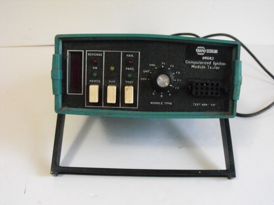
Trying to get a decent deal on a lot of them. I will put them through the hot/cold cycles and test the hell out of them with the tester. See what happens.
il_1140xN.2520705423_mszo.jpg
 
Last edited:
Same ^^^^^ layout as this 1976 Chrysler Electronic Ignition Module from a D100 Pickup pictured below:

This one is a 5 pin, uses the 4 post ballast resistor.

20201102_073427.jpg

20201102_073313.jpg
 
The fifth pin is a resistor internally, should be a 2 pin ballast. Now you can use it in a later model since the plug is not used for that pin.
 
Here is the factory 4 pin ballast resistor with the 5 pin mopar style brain box as set up originally.

I bought this truck from the original owners, all original so I know it had not been changed.

Is this the proper setup for 1976, 4 pin ballast resistor with 5 pin Brain Box?

The top of that 4 pin ballast resistor gets hot and the bottom of it stays cool. Guess that is the way it is supposed to work creating resistance so it goes easier on the coil while running.

20200905_170551.jpg

This is the way it was wired when I bought it and had the 5 pin '76 brain box on it.
 
-
Back
Top