Main dipped headlights not working

-

GJUK

Well-Known Member
Joined
Jun 20, 2014
Messages
139
Reaction score
0
Location
Nottingham, UK
Hi guys

my 1968 dodge dart has no headlights.
I have checked the fuse box which appears fine, the side inner lights come on but nothing on the dipped setting when I pull the knob out.

the side lights go off when it is in fully dipped mode. the rear lights are on just not the front dipped.

Any ideas please on cable colours to trace back, or common areas where to check?

The bulbs look fine.

Thanks,

Jon
 
Check the ground connection at the radiator support. I had mine come loose and lost the headlights.
 
Go over to MyMopar and download free service manuals and diagrams if you don't have them

MyMopar - Mopar Forums & Information - MyMopar Tools/Reference

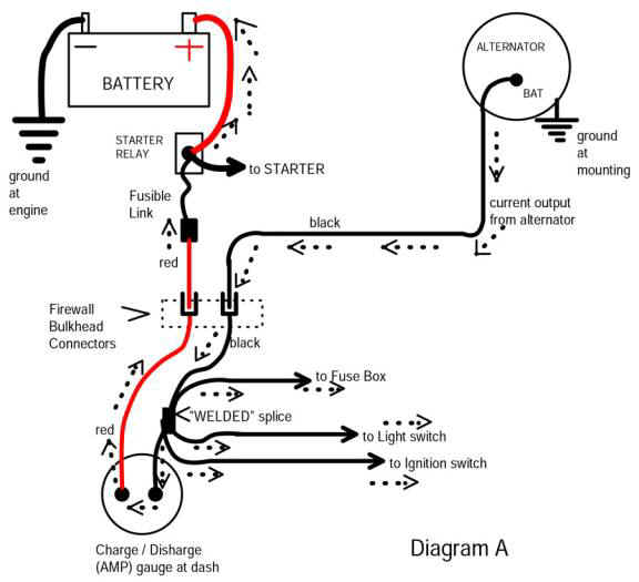
The headlights DO NOT get power from the fuse panel. There are two sources of power to the light switch. The park/ tail / marker and dash lights come off the tail light fuse

But the HEADlights have a splice which comes directly off the BLACK ammeter wire up in the harness. This "main splice" IS NOT FUSED except for the main fuse link. This splice branches off and feeds

ignition switch incoming power

fuse panel hot buss

varies on year to year

and last feeds the light switch for headlights. The light switch has an INTERNAL breaker for protection.

First thing to do is access the dimmer switch. With the light switch in "head" "any two" of the dimmer switch terminals should be hot. If there is only one, you have bad dimmer. If you have two terminals hot, and no lights, inspect the lighting feeds out through the bulkhead / firewall connector, the harness and headlights If no power at the dimmer, time to access the light switch.

Remove the knob by ungrounding the battery, and pull the knob clear out to "head." Reach up around and find the release button, then pull the knob / shaft out of the switch. Now you can remove the switch nut and pull it down out of the panel.

WiringLiteSwBack2.jpg


Then inspect the switch connector, and hook the battery back up, to check incoming power etc
 
67Dart273, you said:
"With the light switch in "head" "any two" of the dimmer switch terminals should be hot. If there is only one, you have bad dimmer. If you have two terminals hot,"
IF you have headlights ON, wouldn't only one terminal be "hot" at a time, (either HIGH or LOW)? Now as I type this, I think I see what you're saying; you will have 2 terminals hot, because if you measure to ground, you will get voltage on the common terminal (feed in from switch) and one or the other of the remaining terminals (HIGH or LOW out) correct?
If that's the case, it wouldn't be "any two" because if you tried HIGH to ground, then LOW to ground, only one of those should be "hot" at a time, no?
Unless I'm confused, in which case anything you can do to help clarify would be appreciated, because I will be needing to wire my project up and I'm hoping to not have a bunch of issues.

I'm talking about the switch "as a whole." You don't even need a diagram to TS a dimmer. There is power into one terminal of the dimmer with the HL switch on so that is one terminal hot

The switch is SPDT, so there is always one output. You don't need to know which one, because if you switch it, the dead terminal should become hot.

Therefore any two terminals should be hot when the HL switch is on.
 
UK to US terminology:

UK "Front and rear sidelights" = US "Parking and tail lights"

UK "Dipped beam" = US "Low beam"

UK "Main beam" = US "High beam"

UK "Dipswitch" or "Dipper switch" = US "dimmer switch"

UK "Earth" = US "Ground"
 
Hi Everyone,

Thanks for the replies.

I have checked the following:

Ground - all fine
all connections pushed home
dash lights come on with the dipped/side lights (low/main beam) so the dimmer switch is working

Before I was playing today I did have indicators...

Now I have No wipers, no indicators and (still) no low/high beam

My 'flasher' works but there is no steady flash. more like Flash...............fla-flash...flash....fla-fla-flash... flash.....whatever flash Totally random.

Something that powers the wipers, lights, indicators must be fouling on something....

Help :)
 
You need to go back and re-read what was said earlier

Have you obtained a service manual and wiring diagram yet?

You may have multiple problems. To repeat what I said earlier:

THE HEADLIGHTS ARE POWERED from an UNFUSED welded splice in the black ammeter wire. This splice/ branch leads DIRECTLY to the headlight switch ONLY for the headlights.

Go DIRECTLY to the foot dimmer switch. See if you have power there ON TWO TERMINALS of the dimmer. Switch the dimmer. One terminal should go dead, the other should be hot. At all times with the light switch in "head" the dimmer should have TWO terminals hot.

From there lamp power goes out through the bulkhead connector another likely spot.

I dislike having to repeat
 
Finding it hard and though I'm sorry you don't like repeating yourself, the information you provided was not very clear.

But the HEADlights have a splice which comes directly off the BLACK ammeter wire up in the harness. This "main splice" IS NOT FUSED except for the main fuse link. This splice branches off and feeds
So it is NOT FUSED, but it is. Got it.

I have a service manual yes.
I have previously bypassed the ammeter - could this cause the problem, sounds like as the power comes from this stretch of cable I may have missed it somehow, does anyone have any photos of where I should fund this under the dash?
The bulkhead connector I have replaced for a new one - these are all sound connections.

Sorry but I've read this four times and it makes no sense.

Go DIRECTLY to the foot dimmer switch. See if you have power there ON TWO TERMINALS of the dimmer. Switch the dimmer. One terminal should go dead, the other should be hot. At all times with the light switch in "head" the dimmer should have TWO terminals hot.

So go to the foot switch, yep. But check something elsewhere, on the dimmer. I thought I had to go to the foot switch... Switch the dimmer, on? Off. dipped, main? What. Which terminal. Huh.

As we are sharing; I dislike extremely long car journeys. :D
 
So, I can see both your points. It sounds as if there is some language barriers as well. Look at what slantsixDan posted. The dimmer switch IS The switch that is operated by your foot, therefore a foot switch. We were trying to make sure you were looking at the right place.
The main black wire from the amp meter is Un-fused in that it does not come from the fuse box. But everything on your car ( except the starter) should be passed through a fusible link at the battery.
There are two circuits that the pass through the light switch. One circuit is strictly for the headlights, be they Main or Dipped. The other circuit is for all the other lighting.
Bypassing the gauge should not cause any problems if you just stuck the two wires together. If you accidentally connected them to earth (or ground), Or to some other circuit, then you may have introduced problems.
 
My understanding was that you had no low (dipped) beam, but your high (main) was working. That is why we were steering you towards the dipper switch. Now as I reread the whole thread, I think I understand that you have no headlights at all.
Based on your other descriptions, it does sound like you might have multiple problems. I think you would do well to ask around and find somebody that has some skills with electricity, and using a voltage meter to trace out your circuits. Make sure you have the printouts of the wiring diagrams And it might help to go to a print shop and have them enlarged.
Because you have problems on multiple circuits, and you have bypassed the amp gauge, you may have disrupted something on the main welded splice that 67Dart273 wrote of.
 
Hi,
Thanks for the reply.

I've read everything everyone has posted, and understand it. Putting it in to action is a bit harder.

Spent all day on the car and I have found the following, which I hope someone can direct me towards where the problem may well be...

Taking readings from the dimmer head light switch.

Ignition on - lights off (pushed in fully)
Brown - 0v
Green with white stripe - 0v
Black with white stripe - 12v
Green lime - 0v
Yellow (2 cables) - 0v
pink - 12v
Yellow Black stripe - 0v
-------------------
Ignition on - side lights lights (pulled out 1 step)
Brown - 5v
Green with white stripe - 5v
Black with white stripe - 5v
Green lime - 0v
Yellow (2 cables) - 0v
pink - 5v
Yellow Black stripe - 5v
-------------------
Ignition on - dipped lights lights (pulled out 2 steps, fully out)
Brown - 5v
Green with white stripe - 5v
Black with white stripe - 5v
Green lime - 5v
Yellow (2 cables) - 0v
pink - 5v
Yellow Black stripe - 0v.


The lime green wire on the dimmer switch looked burnt, I have fixed this now but something has happened here.


pulling the dimmer switch out, 1 or 2 notches makes the lime green lime on the foot switch live with 12v (when disconnected from the foot switch)
HOWEVER, when you plug this in to the foot switch, the 12v stops.... ?!?!?! how what huh...

To clarify, Wipers not working, indicators not working, horn working, 12v at fuses all fine... where is the problem guys ? :(
 
Hi,

I have read:

The windshield wiper and headlamp circuits had circuit breakers in their switches. The back-up lamps and turn signals took their power from the windshield wiper switch, and thus the windshield wiper breaker. The cigar lighter and interior dome lamp get their power from the headlamp switch and use the headlamp switch circuit breaker.

Found here:

How to fix Plymouth Valiant / Duster/ Dart electrical problems

These issues all seem to be linked, where physically in the car do all of these circuits link up please?
 
Hi,
Thanks for the reply.

I've read everything everyone has posted, and understand it. Putting it in to action is a bit harder.

Spent all day on the car and I have found the following, which I hope someone can direct me towards where the problem may well be...

Taking readings from the dimmer head light switch.

Ignition on - lights off (pushed in fully)
Brown - 0v
Green with white stripe - 0v
Black with white stripe - 12v
Green lime - 0v
Yellow (2 cables) - 0v
pink - 12v
Yellow Black stripe - 0v
-------------------
Ignition on - side lights lights (pulled out 1 step)
Brown - 5v
Green with white stripe - 5v
Black with white stripe - 5v
Green lime - 0v
Yellow (2 cables) - 0v
pink - 5v
Yellow Black stripe - 5v
-------------------
Ignition on - dipped lights lights (pulled out 2 steps, fully out)
Brown - 5v
Green with white stripe - 5v
Black with white stripe - 5v
Green lime - 5v
Yellow (2 cables) - 0v
pink - 5v
Yellow Black stripe - 0v.


The lime green wire on the dimmer switch looked burnt, I have fixed this now but something has happened here.


pulling the dimmer switch out, 1 or 2 notches makes the lime green lime on the foot switch live with 12v (when disconnected from the foot switch)
HOWEVER, when you plug this in to the foot switch, the 12v stops.... ?!?!?! how what huh...

To clarify, Wipers not working, indicators not working, horn working, 12v at fuses all fine... where is the problem guys ? :(

You have some MAJOR ground and contact issues.
 
Your voltage reading list is confusing to me.

You have the

LIGHT SWITCH

This is the dash mounted switch which turns on the park, tail and head lights, and twisting the knob on that switch controls the dimming of the dash cluster illumination lamps

The light switch has TWO power sources

1....UNFUSED power (originally) came through battery---fuse link in the engine bay---bulkead connector (large red) ..........to ammeter......through ammeter.....large black........TO FACTORY WELDED SPLICE.......branch off to headlight switch. THIS WIRE IS HEADLIGHTS ONLY. It does not power dash lamps, tail/ park / marker lamps

2....Power for tail / park / marker / dash lamps comes from the tail fuse in the fuse panel, and of course this is hot all the time.

THE BUSS in the fuse panel which feeds that tail fuse gets it's power also from the WELDED SPLICE in the ammeter black ammeter wire.


Now, with the headlight switch turned on to headlamps, ONE wire feeds from the dash mounted light switch down to the foot operated dimmer switch. That is a simple SPDT switch which simply feeds that one wire power to one or the other output terminals

An aside, from the Mad Electrical article.....showing simplified primary wiring

Catalog

amp-ga18.jpg


Notice the WELDED SPLICE branches off. There are NO fuses in that circuit except the "fuse link" which is poor protection. The ONLY protection for the headlight circuit is a built in circuit breaker in the headlight switch.

The following refers to the 68 PLYMOUTH manual as downloaded from MyMopar

MyMopar - Mopar Forums & Information - MyMopar Tools/Reference

This is only because there is no Dodge manual on that site for that year

68 Plymouth, page 335 (8-109)

"Front end lighting" The singe wires coming out of the bulkhead connector branch off and feed high beam and low beam filaments

"Y" in the bulkhead connector, wire L3-18R

and "X" in the bulkhead connector, were L418V

Those two wires come directly from the foot dimmer switch

NOTICE the grounding. NOTICE the grounding all connects to one point. "Single point of failure." That ground MUST be well made and in place. "Interesting" effects are caused if that ground is poor or broken due to backfeeds in the circuits.

frontend.jpg
 
Last edited:
Headlight switch Looking down on top of the switch is exactly how this is layed out

"B1" is main headlight power "coming in" (L1-16BK) THAT IS the unfused power coming from the black wire splice in the ammeter wire

B2 powers tail / park/ marker and dash lamps. This power comes from the tail fuse in the fuse panel L8-18P

Terminal "D" at top right, with the yellow wires, is the switch for the dome / courtesy lamps. This is grounded through the switch frame and dash when the switch knob is "clicked" far left. This does the same thing as the door switches. "Map switch" lighting complicates this circuit

"R" is the "rear" or tail lamps but this also feeds side marker lamps L17-18BK and L2-16DGM

"P" is front "park" lamps L6-18Y

The "H" terminal is incorrect. "H" is headlight power out TO the foot dimmer switch L2-16LGN

the TAN there should go to the adjacent terminal, E1-18T. THAT WIRE is a "trick." That is the output of the dash dimmer lamps control. Power from that comes from the tail fuse, is hot with the switch in either park or headlight, with the dash dimmer control twisted to the left. That wire is then "hot" and feeds power TO the INST fuse in the fuse panel, out of that fuse on ORANGE wiring to all of the different dash and cluster illumination lamps, radio dial, etc

headswitch.jpg
 
Last edited:
Foot operated dimmer switch

Notice the GREEN wire L2-16LGN, sound familiar? That is power TO the dimmer switch FROM the light switch. I am not worried here, about old theory current flow nor electron flow, I'm speaking "functional" flow that is from the battery through the various points to ground. So to / from refers in reference to the power source, not physics

The other two wires, marked H and L for hi/ lo, simply go through the bulkhead connector, out to the previous diagram of the under-hood wiring.

At some point, the high beam wire branches off to feed up to the hi beam indicator in the cluster

dimmer.jpg
 
You need to look at the factory manual I referenced earlier and use the terminology in those diagrams. That is the only way we will know what you are talking about.

I will say this.........your LOW readings pretty much everywhere indicates a failure at a major point. Start with the Mad article / diagram. Check primary power and follow it to major checkpoints

The entire reason for the Mad article is that the bulkhead connector / ammeter is subject to failure

OTHER failure points in no particular order, due to heat / vibration /corrosion / combination, "etc"

Any and all bulkhead connector terminals. TAKE IT APART and inspect the terminals

Bad connection at / in the fuse link. These can corrode internally either the wire and or the terminal

Ammeter. Loose connections, internal problems in the ammeter, as well as actual failure in the crimped eyelet ends

RARE BUT HAS HAPPENED. Failure of the factory welded splice. There is only one way to inspect this, and only so many ways to find it.

AGAIN...........that splice is a major connection. The power path is battery......fuse link....bulkhead (RED).........through ammeter........(BLACK)..........and to that SPLICE

The splice branches off and feeds

Headlights ONLY power to the headlight switch

main power feed to the ignition switch

hot buss in the fuse panel

Depending on year / model, one or two other items

HOW TO FIND?

You need to LOAD that circuit, IE turn on the headlights. Check headlight power at B1 at the headlight switch WITH LIGHTS TURNED ON

If that reading is much below "battery" you have a lot of voltage drop. Check at the terminations you can REACH. That is you cannot (presently) access the splice

So check at the ammeter, bulkhead terminal, fuse link. If those points are GOOD and the actual wire at the light switch is low, then you need to check the splice

A "secondary" check is to also check power coming into the fuse panel with a load applied. Turn on what you can.........dome, tail, lights, and check the power at the panel buss. If that's low, this confirms, a voltage drop. That power comes from the very same ammeter / black wire / welded splice

HOW TO INSPECT........only one way.......drop the column.......pull out the cluster, and access the harness. Start at the ammeter black wire, and cut / untape the harness a few inches, following the black wire, until you find the spice, wrapped up in the harness.

It is rare but it DOES happen. I found the first failed one of these I ever found in the early seventies, at NAS Miramar, San Diego. This was a friend's 68 Road Runner. We had the entire dash torn apart with my 69 Plymouth manual on my lap.
 
Hi,

Thank you for the replies I have been on the car all day today so here is what I have found and I will read through comments in depth shortly.

This is my wiring - I have done the MAD 'upgrade' and cut out the AMP gauge.

IMG_20160528_163116.jpg


I have had the entire wiring loom apart today, found all three splices.

Here is a video of the car with the 'flashers' on. You can see they are flashing randomly but they do work.

View My Video

The new fuse box, I have checked this 20 or so times that it is the same as the original.

IMG_20160528_163141.jpg


I found this splice under the dash. I disconnected all of the wires in order to try and find which circuit was at fault.

When the two on the left were 'rejoined' to how they were (factory splice) the reading on the gauge drops and pulses...

IMG_20160528_163316.jpg


This image shows the red cable from the starter relay +, then to the black cable (as the amp gauge has been bypassed)

IMG_20160528_163444.jpg


I do get a reading on the plug which goes to the foot pedal switch when the dimmer switch is pulled out fully, only 5v though not 12. HOWEVER, when the plug is in the switch I get 0V on the same connector.

IMG_20160528_163739.jpg

The lime green wire going to the dimmer switch for the low and high beam was burnt in the dimmer switch (where this photo shows the test probe in) I have now fixed this with a new connection.

IMG_20160528_163715.jpg


IMG_20160521_130434.jpg
 
OK let's step back, referring to your own hand drawn diagram. It seems to me we have a basic power problem that is affecting the ENTIRE interior of the car.

This is based low? readings at the headlight / dimmer switch which is "most directly" supplied.

Also, your 4X / hazard flashers are supplied off the "hot" buss in the fuse panel, and that wire is also pretty "directly" fed.

So you need to backtrack from there

What have you changed? from original in the power path to the light switch / ignition switch?

Did you eliminate the bulkhead connector terminals for the "big" red? If not I would start there and at the fuse link.

REMEMBER you cannot check this stuff WITHOUT A LOAD. So you need the lights on, etc, to load down that circuit.

How did you bypass the ammeter? Check that connection!!! Between the old "big red" and the "big black" at the ammeter (originally)

If / when you start to get this straightened out, and since you have a new fuse panel, I would try and add some things to "fused." Wipers for example.

If / when you find the trouble at the headlight switch, and if the ignition switch is still low, "it's simple." You need a load on the switch, heater, ignition, signals, something. With that load, check the switch "coming in" and "going out" Should be obvious if the switch is at fault.
 
OK let's step back, referring to your own hand drawn diagram. It seems to me we have a basic power problem that is affecting the ENTIRE interior of the car.

Thanks for your reply again! Yes I agree

This is based low? readings at the headlight / dimmer switch which is "most directly" supplied.

It appears so, even at the battery, in the boot. with a ground earth and on the 12v + on the battery I get only 5v reading. Take the battery off of the car and it is showing 12v. There must be a ground out live somewhere?

Also, your 4X / hazard flashers are supplied off the "hot" buss in the fuse panel, and that wire is also pretty "directly" fed.

Yes, on the first splice I can see where they feed from. The splice looked fine

So you need to backtrack from there
What have you changed? from original in the power path to the light switch / ignition switch?

I have changed the fuse box (video of this soon but it compares the same as to the one I removed)

Did you eliminate the bulkhead connector terminals for the "big" red? If not I would start there and at the fuse link.

Yes, this connector has been changed months back, all working fine for a good while (though no headlights, my wipers and indicators were working if a little erratic at times). Video of this connection also soon.

REMEMBER you cannot check this stuff WITHOUT A LOAD. So you need the lights on, etc, to load down that circuit.

Thanks.

How did you bypass the ammeter? Check that connection!!! Between the old "big red" and the "big black" at the ammeter (originally)

Took the connections off the back, soldered them together. Red to Black.

If / when you start to get this straightened out, and since you have a new fuse panel, I would try and add some things to "fused." Wipers for example.

Yeah.

If / when you find the trouble at the headlight switch, and if the ignition switch is still low, "it's simple." You need a load on the switch, heater, ignition, signals, something. With that load, check the switch "coming in" and "going out" Should be obvious if the switch is at fault.

Are there any in line fused links I should try and find to see if they have burnt out?

Thanks again
 
-
Back
Top