Alternator Question

-

Fishthatkills

Fish that kills
Joined
May 5, 2009
Messages
431
Reaction score
2
Location
Austin Texas
Way back (17 years) when I first got my motor running I bought an alternator for my car and turned in the "old" one as the core. It had a one groove pully on it.

Saturday night I went to a cruise and upon leaving, my car would barely turn over and to make a long story short my lights quit working on the drive home. I did get a jumpstart and barely made it home. Crappy end to a great cruise!

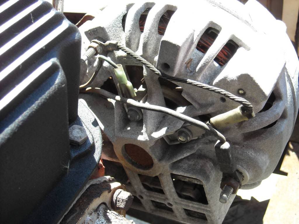
Sunday I removed the Alternator and had it tested at O'Reilly's. It failed! When the guy was connecting it to the machine he put on a pig tail with three wires. One to the field, one to the battery or big post, and one to a ground connection. My car has two wires only. One ring connector that goes to the big post and another that connects to the field. Am I missing the "ground" wire that should be connected? Looking at the FSM I see that they show all three points on the picture they have, It does not say that the ground is connected.

When I replace the alternator should I use a wire to ground that terminal?

Is there a quick way to check the output while it's in the car and running?
The options I have are a 60 amp two pully or a 50 amp single pully. I do not have any accsessory gizmos on the car so I don't need a lot of amp's do I? Not wanting to re-wire the car at this point. I have a week till the Lonestar HotRod Round-up and need to get it ready.


John D. Beckerley
Austin, Texas

:rock:
 
sounds like you had a dual fld alt on a single fld charging system.

what regulator you using? stock style??


the proper alt for your car assuming that you have a stock charging system and the cuda in your avatar is your car will only have the big wire and a small fld wire.

if the alt has the large wire and two small fld wires then its for a dual fld systema nd you get it to work on your car by grounding one of the fld terminals on the alt.


that make sense? lol
 
I second aboves, w/ more details:

My '69 Dart had a single field wire (round alt, 30A?). The other field connector grounded thru the alternator frame. The voltage regulator applied 12 V to the field - on/off in original mechanical solenoid type or 0 to 12 V proportional (I think) for later upgrade electronic ones (made to look like original). I once thought the alternator was bad, but the new one acted the same. I fixed it in the Auto Parts parking lot and got a refund. It wasn't getting a good ground thru the frame (alminum is bad for that). I ran a separate ground wire to the 2nd connector.

My '82 Aries (square-back alt) used 2 field wires, one was constant +12V and the return controlled by the electronic regulator. They did this because easier to regulate on the low side. It also cures the problems of relying on the frame ground.

Look close at your field terminals (brushes). For your car, the one without a wire should not have an insulator and should clamp against the aluminum frame. If so, remove and sand the aluminum. If isolated and has a spade terminal, that is OK. Run ~14 awg wire from it to a good engine ground. That is better than relying on the frame ground anyway.

If your ammeter works, you should see when the alt is charging or discharging. If the alternator isn't working, you will just barely see the needle leaning towards "D", more if the high beams are on. You can over-ride the regulator by disconnecting the field wire (marked "F", small bolt I recall) and connect it to the 12 V battery post. You should then see the ammeter go strong towards "C". If your ammeter is broken, the alternator can't charge the battery (all output goes thru ammeter I recall). To check, measure the resistance from the large wire at the alternator (disconnected) to the battery +12 V, or between the two bolted terminals on the firewall (disconnected). I would guess <10 ohms. Check your wiring diagram first since from memory. If you don't have a multimeter, they are $3 at Harbor Freight. I keep one in every car.

Later cars dropped the ammeter and put in a stupid "low battery" light. By the time that comes on, you have big problems. That stranded me multiple times in my '82 S-10 and Aries. I tested the Aries by breaking the large alternator connector in the engine compartment and putting a 100 A meter in series. A classic hobo test is to start the engine and disconnect the battery. It should run on the alternator output alone. This was claimed to possibly damage later electronics ('80+). You don't need either since you have an ammeter built in.

I think the original 30 A alternator should be fine. I think some were 40 A, and JC Whitney long sold an upgrade kit (field coils & diodes?) that gave more. The later square-back alternators should bolt-in. I think rated 70 A. The one in my Aries fried the diodes every year, always the set "hanging in the air" not the ones bolted against the frame. An auto electronics shop confirmed my experience. The square-back is great for looking to see if they vaporized again. I got good at taking the alternator apart underneath the AC compressor and replacing just the diode bar. By cutting slots in the diode bar for cooling I got them to last 2 years. The 60's alternator with big diodes pressed into the frame can't be beat for reliability and they look better.

I recall mention that later alternators (Denso?) can bolt in, but never tried. Not sure if some came with a V-belt pulley or if you can swap pulleys. Also, you would need to change connectors. They are small, light, reliable, and put out ample current (100 A?), but 30A should suffice for you.
 
Yes, Looking at the schematic I should have only two wires. The terminal on the back marked "ground" is not used correct? or do I ground it to the alternator itself?
There are three marked or named. One small terminal marked Field, One big lug Battery, One small terminal marked ground.

No electrical changes other than a electronic ignition have been made to the car. 96% original. Stock style regulator but electronic not mechanical. Otherwise also old.

John B.
 
Fishthatkills,

As stated above, the field terminal marked "ground" must electrically connect to engine ground. If not, no field current can flow and the alternator will not output current. Reasons why it might not get grounded:
1) Corrosion at interface between the brush copper to the alternator frame or corrosion from the alternator frame to the engine.
2) You have a later style brush installed for the "ground" one (70's square-back alt). I recall they can interchange. The later ones are isolated from the frame. See above to fix.

Things to check (engine running):
1. Whenever there is ~12 V ACROSS the field terminals, the alternator should put out full current (~30 A).
2. If not, verify there is ~12 V from the "Field" terminal to battery ground.
3. If not, the problem is in your voltage regulator, assuming your battery is low and needs charging current.
4. If OK, verify you have <1 V from the "ground" terminal to battery ground. If not, turn off the engine and locate the main resistance using your DMM - terminal to alt frame, alt frame to engine, engine to battery gnd.
5. With above understanding, you can manually actuate the alternator by applying voltages to the field terminals.
6. To measure alt output, use your dashboard ammeter "ALT". If broken (resistance >1 ohm), bypass with a wire at the firewall connector on engine side (larger bolted terminals). You will then be flying blind on alternator output, just like most cars since 1982.

Good luck. Re-read everything in posts above. Buy a DMM if you don't have one. Learn how to make simple electrical measurements and understand the difference between voltage drop and current flow. Wikipedia is a good start.
 
Man am I so glad I installed a ONE WIRE unit on my duster. It works so good and less wires. If you try it I bet you'll wonder why you didn't do it sooner. It won't work for you number perfect folks I know so hold the mad mail down guys. I don't want mine perfect just fast and simple.
 
All you have to do is remove the insulator from the screw on the field terminal that you are not using. You can do it that way or you can run a wire from that terminal to the case as a ground.
 
You can see in this pic that I just attached a ground to one of the field terminals. Either way is fine. The insulator is the piece of plastic that is under the field terminal screw. This alternator is from an 85 New Yorker. I do not think it matters which field you ground.
88ddd903.jpg
 
I now have CHARGING!!! YEE HAA! I connected the second field wire to the alt chassis ground and VIOLA! Now shows charging and even with the brights on!

Thanks FABO! Ya'll are the greatest!

John B.
 
-
Back
Top