Anybody have a diagram or schematic of the alternator? I couldn't seem to find the actual one for the 70's style alternator with alternator/battery connection and two field connections. I just wanted to see what was happening internally with the field windings.
You are using an out of date browser. It may not display this or other websites correctly.
You should upgrade or use an alternative browser.
You should upgrade or use an alternative browser.
Alternator Wiring Diagram
- Thread starter 68coupe
- Start date
-
67Dart273
Well-Known Member
Only difference between 69/ earlier, and 70 / later, is that the 69/ earlier has one brush grounded, and one brought out to a terminal
The 70 / later, properly known as "isolated field" removes that ground and has both field terminals brought out to quick connect terminals.
You can use a late alternator with an early VR by simply grounding either brush.
What specifically are you doing, IE converting to later VR, or what?
The 70 / later, properly known as "isolated field" removes that ground and has both field terminals brought out to quick connect terminals.
You can use a late alternator with an early VR by simply grounding either brush.
What specifically are you doing, IE converting to later VR, or what?
No, not converting or upgrading. I'm just helping him to troubleshoot the charging system problems that he currently has. The actual problem was using BWD brand voltage regulators. Seems 9 out of 10 are defective out of the box.
I just wanted to know what the actual wiring and circuitry was internally to give me a better understanding of the operations. It's been about 30 years since I was tearing into alternators. It's been a long time since I built a bridge rectifier or a diode pack!
I just wanted to know what the actual wiring and circuitry was internally to give me a better understanding of the operations. It's been about 30 years since I was tearing into alternators. It's been a long time since I built a bridge rectifier or a diode pack!
abodyjoe
Well-Known Member


67Dart273
Well-Known Member
No, not converting or upgrading. I'm just helping him to troubleshoot the charging system problems that he currently has. The actual problem was using BWD brand voltage regulators. Seems 9 out of 10 are defective out of the box.
I just wanted to know what the actual wiring and circuitry was internally to give me a better understanding of the operations. It's been about 30 years since I was tearing into alternators. It's been a long time since I built a bridge rectifier or a diode pack!
OK if you are tearing down a stock Mopar alternator you need a shop manual. You can download many over at MyMopar. I would download whatever applies to the actual car, and for the old vs newer alternators, download say, a 69, 70, 72, and 73 shop manual
69 of course still had individual soldered diodes, and a grounded brush
70 was first year of isolated field, was still a "round back" with soldered diodes but had isolated brush holders
Somwhere around 72 ish 73 ish Ma went to the "square back" design with the integrated "diode bridge."
All this is clearly laid out in the manuals
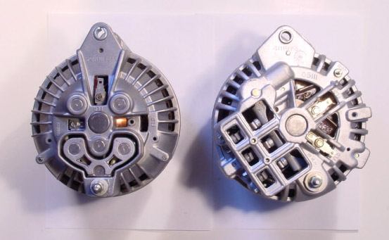
Comparison of round / squareback units. I've never actually seen one like the left. Sharp eyes will see it's equipped for BOTH the earlier grounded brush (installed) as well as both brushes isolated (the empty one at 3 O'clock
This is a screenshot right out of the 72 shop manual. By the way, this very manual was provided by AbodyJoe
Attachments
He just put a new Duralast regulator on and at higher RPM's it goes to nearly 17v. Do the field wires (blue and green) go to particular FLD terminals? I think he has green to the outside terminal, blue to the inside. This is new alternator and, as stated, new 2-wire voltage regulator. I made sure that he cleaned the firewall and VR and added a ground wire to the engine on one of the mounting bolts.
That's one of the reasons I wanted to be able to see the internal wiring, to determine where the field wires should be connected.
That's one of the reasons I wanted to be able to see the internal wiring, to determine where the field wires should be connected.
I'm not dismantling anything. He's about 200 miles from me. I'm just trying to help him determine why the alternator is not charging. He has replaced both alternator and Voltage regulator. Jumping the plugin on the VR (blue and green wires) and bringing engine up above idle he now gets nearly 17v. Taking the jumper out and putting the VR back in he still gets nearly 17v. All wiring seems to be intact and functioning as designed.
He's a young guy with limited resources, so I'm trying to help out. Now you know as much as I do about it LOL. He did buy a new multimeter today, so that helps! Thanks guys
He's a young guy with limited resources, so I'm trying to help out. Now you know as much as I do about it LOL. He did buy a new multimeter today, so that helps! Thanks guys
67Dart273
Well-Known Member
I wish you guys would ask "the real question." It would save all of us a lot of time
Jumpering as he did proves
the alternator can charge
the output wire from alternator to battery is probably OK
=======================================================
So now we should concentrate on the field / VR circuit. Once again, the shop manual is the bible. There is no excuse for not having one, as they are free
The blue VR wire goes to switched 12V ignition. The green VR goes to one brush, and the remaining brush goes also to switched 12V ignition.
SO. We need to determine IF the VR circuit "has control." This would be EG if the rotor is shorted or one brush (green) is grounded. EASY. Unhook the green wire or unplug the VR It should STOP charging.
NEXT is make ABSOLUTELY certain the VR is grounded. MUST. Scrape the firewall / VR clean at the mount and remount TIGHT. Use star lock washers.
WORK the VR connector in/ out a few times to scrub it clean and "feel" for tightness.
If no joy on the above, next, pull the VR plug. Should stop charging. If it does, devise a way to jumper across the two VR terminals. Next, remove the BLUE wire at the alternator and GROUND that alternator field terminal. Should charge "full output."
If it does the above, replace the VR BUT BEFORE you replace it, CHECK the amperage draw on the field
Again refer to the shop manual, they tell you how. Turn the key to "run" with belt removed, engine stopped. Disconnect the green field wire, and hook an ammeter from that field terminal to ground. Turn the pulley slowly. You should get an "averaged" field current draw. If it's approaching or above 6A this might be "taking out" the VR.
If it's down around 4A or less, replace the VR
67Dart273
Well-Known Member
So far nobody has answered "the real question". I asked for an internal wiring diagram of the alternator. I still don't have that. But, thanks anyways.
Geezuz Christ. Am I getting PAID for this. Tell me THIS!!!!!!! Why do you NEED this? You CERTAINLY don't need it to troubleshoot the damn thing. Did you download the shop manual. DID YOU?
It's a rotor. with brushes. All two of em
It's a stator. All automotive alternators have THREE wires unless they are "Y" wound in which case there are FOUR. Often, the pigtail is not used. Some are Delta wound
These three wires go to three positive diodes and three negative diodes.
Every fricking Ford, GM, Mopar, Datsun etc etc etc etc etc etc etc etc alternator I've had apart is wired the same way.

You know, sometimes when somebody asks what time it is, they don't want you to tell them how to build a clock!! I can fix a charging system, have fixed a hundred of them. If you will read the original question, I asked for a schematic - not a dissertation on converting or upgrading or the historical difference between Chrysler charging systems. I've thanked you twice, what the hell more do you want? Damn, no wonder I don't ask any questions on here anymore.
Thank you for the ignore list entry - maybe someone else will get a chance to correctly answer a question. BTW, I thought you were going to take a break from FABO. Do everybody a favor.
You got that right, Redfish.
You got that right, Redfish.
Rustedwrench
Well-Known Member
You could not be working harder at this than if you were trying to pick fly poop out of pepper. Stop and think what determines the charging system voltage. It is determined by the voltage seen by the voltage regulator. If the alternator is working correctly and the voltage the regulator senses is too low the charging voltage will be too high.
Perhaps some voltage testing is in order instead of throwing parts over and over.
Perhaps some voltage testing is in order instead of throwing parts over and over.
I was just trying to help a guy that doesn't have a lot of experience with cars.
I had three years of electronics in high school and two years of circuits in college before transferring to mechanical engineering. I had a rewarding career in IT Management. Thanks, but I don't need help in troubleshooting a simple automotive charging system.
Everything that 67DART273 posted is easily attainable on the internet with a simple search. All I asked for was a schematic or wiring diagram of a Chrysler alternator. He was the one questioning me about what I was doing. I neither needed his help nor asked for it and it turned into him pitching a tantrum tantamount to a 3 year old kid.
As far as I'm concerned, thread closed.
People need to carefully read the posts with some comprehension before going off telling someone what they need. But, I would like to sincerely thank anyone that answered with the intention of helping.
As far as I'm concerned, thread closed.
67Dart273
Well-Known Member
You don't need "an internal diagram" to fix this. Everything I posted is exactly and directly relevent to this problem. I you are so damn smart and have had all this electronics you don't need anybodies help on here.
Either go fix this, or go "google the internet" since you know so much
Either go fix this, or go "google the internet" since you know so much
BillGrissom
Well-Known Member
68coupe,
Why are you still ranting? The schematic you asked for is in post #11. It is a very simple system and clear to anyone who knows basic electricity. We can answer any other tech questions you have. It usually does help when people tell us their final goal, otherwise they rant, "too much detail".
Why are you still ranting? The schematic you asked for is in post #11. It is a very simple system and clear to anyone who knows basic electricity. We can answer any other tech questions you have. It usually does help when people tell us their final goal, otherwise they rant, "too much detail".
straightlinespeed
Sometimes I pretend to be normal
I was just trying to help a guy that doesn't have a lot of experience with cars.
Everything that 67DART273 posted is easily attainable on the internet with a simple search. All I asked for was a schematic or wiring diagram of a Chrysler alternator. He was the one questioning me about what I was doing. I neither needed his help nor asked for it.
People need to carefully read the posts with some comprehension before going off telling someone what they need. But, I would like to sincerely thank anyone that answered with the intention of helping.
As far as I'm concerned, thread closed.
Enough is Enough! You posted on a internet forum where you asked for peoples help, not one specific person but anyone. 67Dart273 was nice enough to ask some questions to try and help you out and he provide you said schematic.
Quit the bickering and name calling, and work together to solve your issue.
-


