Charging Gremlins

-
Back to work. Okay I just checked the voltage at the blue trace wire on the ign terminal with the key on run. Posiitve probe on batt pos and neg probe in the ign terminal. I have a reading of .36
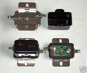
This is a new regulator. While the car is running at idle the voltage across the batt is around 12.5. as I raise rpms the volts keep rising to about 15.
As far as testing the grounds if I remember correctly that was car running test with the neg probe on batt neg and the pos probe on the regulator mounting flange. With car running it is reading -.001 that doesn't seem right ?? I checked to see if it was grounded by putting the voltmeter on batt pos andprobe to the case and got 12.6 volts so it is grounded.
Where does the blue wire on the ballast come into play
for the hell of it I checked the blue wire there with the engine off and key on run test and came up with .45 voltage drop ?
Sory for the long just trying to be as thorough as I can
Luke
 
Back to work. Okay I just checked the voltage at the blue trace wire on the ign terminal with the key on run. Posiitve probe on batt pos and neg probe in the ign terminal. I have a reading of .36

This test must be done with key in run but engine not running----is this the case?


with the neg probe on batt neg and the pos probe on the regulator mounting flange. With car running it is reading -.001 that doesn't seem right ??

Only thing you could possibly get better is zero. That is fine


Where does the blue wire on the ballast come into play
for the hell of it I checked the blue wire there with the engine off and key on run test and came up with .9 voltage drop ?

You must have done the first test (at top of post?) with engine running? Sounds like you have just "properly" done the first test. The "key side" of the ballast is the same electrical point as the IGN terminal of the ballast.

This last IS the problem. You are losing voltage all the way from the battery, through the harness, connections, and switch, to the regulator.
 
On the ballast connection I meant to type .4 but put .9 instead I edited it after I realized my mistake.
Yes the first test I did was key on run engine off checked at the bottom post of the regulator on ign terminal .36 is close I hope. do you think that running the older style regulator with the electronic ignition is coming into play ? I can post some pics of the electronic ignition if it would help. If the electronic ignition was meant to have 2 field wires blue and green how could this work with one green field and the other field going to ground? Pulling my hair out
Luke
 
Here's a couple pics of the ignition
olhh.jpg

eb7x.jpg
 
Maybe these simplified diagrams will help. Now since you did the MAD bypass, some of this will be different, but past the bulkhead it's still essentially the same. Follow along........

The top photo merely follows along from the factory diagram, and the bottom diagram is a simplification.

In the bottom diagram, You would have seem to have eliminated between the battery and "2" as you have done the bypass. In a stock system, that no2, the point at which the battery feed passes through the bulkhead is one point at which voltage can be lost---due to a bad connection

The same is true of "3, 4, 5" which is the two ammeter connections and the ammeter itself

"6" represents the in--harness welded splice, which is a JUNCTION in the black ammeter wire a few inches down into the under-dash harness, all taped up in the harness. These do not fail very often, but they CAN

The next point in the path is PROBABLY your first point of attention. "7"represents the main black supply going INTO the ignition switch, and this could be a point of bad connection

"8" represents the switch itself -- the switch contacts could be going bad

"9" represents the outgoing terminal of the ignition switch, fed out on the dark blue "run" wire, and this is yet one more possible bad connection

"10" represents where the dark blue "run" wire comes through the bulkhead connector and of course is just one more point of possible loss

"11" represents the common point at the switch side of the coil ballast resistor AND the regulator IGN terminal. This second point where you have your meter, and so EVERYTHING in between the battery and "11" is a suspect area
 

Attachments

  • _MG_7615cs.jpg
    48.3 KB · Views: 131
  • _MG_7616cs.jpg
    46.1 KB · Views: 117
On the ballast connection I meant to type .4 but put .9 instead I edited it after I realized my mistake.
Yes the first test I did was key on run engine off checked at the bottom post of the regulator on ign terminal .36 is close I hope. do you think that running the older style regulator with the electronic ignition is coming into play ? I can post some pics of the electronic ignition if it would help. If the electronic ignition was meant to have 2 field wires blue and green how could this work with one green field and the other field going to ground? Pulling my hair out
Luke

OK, so now we have changed things. You are measuring .36 in one case with engine off, .4 in the other which is "mighty close."

You have not unhooked anything, is that correct? The ignition and regulator, as well as all alternator wiring, is all hooked up as per "normal?"

And did you say this is a new regulator?

(Looking at the photo of your regulator, I would bet that it IS an updated electronic regulator)

Make CERTAIN that the IGN terminal connector is nice and clean and tight.

The regulator may ALREADY be a replacement electronic. Look underneath the regulator. If there is two large resistors, it's the older "relay" type like this

http://www.fuelpumpsusa.com/AUTOPARTS_PICTURES/aftermarket/v15/aftermarket_v15_2.jpg

or this:

440-1621-large.jpg


However, if there is NO resistors on the bottom, it is already an updated electronic regulator

Like this one

80f4_35.JPG


Or this little short one

mIoYS7vG16yoU0jw7VAGiYQ.jpg
 
Yes it is still hooked up. I just checked per your second sketch, so here we go.
point # 1 the fuse link the voltage drop is .046
point number 2 the bulkhead connection I deleted and soldered
I checked it after my soldered splice voltage drop is .057.
Points 3,4 ,and 5 ammeter connections were deleted due to splicing
but I checked after the splice and it is .07 voltage drop.
I skipped the welded splice(point 6) to avoid unwrapping all the tape and went to point 7 black in on the switch and got .3
I do not know how to test the switch ( point 8) so I skipped it and checked
blue wire (point 9) .3
Looks like I better unwrap the welded splice, do you agree ?
I can't thank you enough for your help.
Luke
 
The thing is, now that you've corrected your readings, everything looks fine in that dept.

That's why I say "now we've changed the problem" because it now appears there is NOT a voltage drop issue.

As long as you are certain that the IGN terminal of the regulator is good and tight, this looks like either a regulator that's off, or else a battery problem, or, crap.........maybe your meter is wrong, and that CAN happen

Here's what I'd do next

1--If possible round up a friend, etc, and check that your meter agrees

2--Make absolutely certain that the regulator IGN terminal is clean and tight.

3--If you have a rig with another battery you can borrow, switch batteries

4--If none of the above change anything, replace the regulator.

If you do replace the regulator, now would be a good time to decide if you want to convert to the 70 / later unit, but since most / all replacement 69/ earlier regulators are actually solid state, I'm not sure there's an advantage.
 
so you do not think the .23 jump between my bulkhead splice and the black in on the ignition is cause for concern. it has to be at the welded splice.
My overall reading at the ign terminal is .36 do you think that that is good enough? I'll put my old regulator back on and give it a shot.
Luke
 
so you do not think the .23 jump between my bulkhead splice and the black in on the ignition is cause for concern. it has to be at the welded splice.
My overall reading at the ign terminal is .36 do you think that that is good enough? I'll put my old regulator back on and give it a shot.
Luke

If you are measuring that with the alternator and ignition wiring all hooked up, then voltage drop is not the issue. I would consider less than .4 to be acceptable. I usually post ".3" but you are still way less than 1/2 volt.

Dave ("KitCarlson") mentioned earlier, ---you might double check this a different way.

With everything all normal, warmed up, and running at fast idle, measure across the battery accurately

Then measure from the IGN terminal of the regulator to ground.

The difference between these two readings should be close to the reading you just posted, or about .36

I don't know how we got so far off track, here. I may have got you onto the wrong terminal of the regulator initially.
 
I had the same problem. Turned out to be the ground wire on my battery. It had corrosion intertwined in the wire braid throughout, under the black plastic housing. it worked fine at idle and parked, but when i was driving it was a different story. I went through 3 regulators, a ballast resistor, a relay, a spool of wire and even replaced the alternator "just in case". Friggin eleven dollar cable did me in. I replace it and no more problems. I cut the sheath off just effing around and the corrosion I saw was a surprise.
 
The thing is, now that you've corrected your readings, everything looks fine in that dept.

That's why I say "now we've changed the problem" because it now appears there is NOT a voltage drop issue.

As long as you are certain that the IGN terminal of the regulator is good and tight, this looks like either a regulator that's off, or else a battery problem, or, crap.........maybe your meter is wrong, and that CAN happen

Here's what I'd do next

1--If possible round up a friend, etc, and check that your meter agrees

2--Make absolutely certain that the regulator IGN terminal is clean and tight.

3--If you have a rig with another battery you can borrow, switch batteries

4--If none of the above change anything, replace the regulator.

If you do replace the regulator, now would be a good time to decide if you want to convert to the 70 / later unit, but since most / all replacement 69/ earlier regulators are actually solid state, I'm not sure there's an advantage.
I did all of the above checks. Went to parts store and bought a solid state regulator all they had was the smaller one like in your pic a few posts ago.
After I installed it I figured I'd check the voltage drop again and it is now at .3 even at the ign terminal. Still at idle across the batt I am looking at 12.8 volts and the highest I can the bat to read at increased rpm is 13.8.
I feel like I am getting close do you agree. ?
Thanks
Luke
 
13.8 when running fast is as close as you will ever get!!!

Now, the last part of the equation is, "is the alternator healthy?"

Let's imagine that you have one blown diode out of the 6. This will drop the output current of the alternator by a considerable degree, but it will increase the AC hash and ripple.

One thing you can do is with the engine running fast, and headlights, heater on, see if the voltage maintains at 13.5 or better, and the other thing you can do is to switch your meter to AC volts and read across the alternator output stud to ground. You will be reading what is called "AC ripple" and there should be a very small reading, the smaller the better. Less than 1/2 volt (.5) is good

So...........what did you change to get this to shape up? You did check charging voltage after the MAD mod, and no change, is that right?

Was it the new regulator?
I got the higher rpm charging volts up to 14.1 volts now by replacing the battery cables. It will not get higher than that. At idle it still reads about 12.9 to 13 volts. Ideally I would like to see 14 volts across the board if it is not out of the question but maybe I am being to picky. I do know that it will not overcharge now and that was my main concern.
As most of you know I am new to Mopars and I am not a wiring expert. Hell I just got this car last week and now I'm learning how to test for voltage drop ?? I am pretty ocd when it comes to things working properly but we got it figured out. I've been messing with this wiring for 2 days now, but all frustration aside I learned a ton about the car by unwrapping tape, cutting my forearms from reaching under the dash, and actually reading wiring diagrams. Here's a pic of the through bulkhead connectors.
0ff8.jpg

Voltage loss, Fire hazard ? you bet.
Here's a pic of the welded splice, I was already in this deep so I just had to see it. It's just a little past the halfway point in the harness coming from the bulkhead up the steering column.
kfe.JPG

Mine was fine.
 
13 V at idle sounds fine. It is at least keeping up with the load and not discharging the battery. At higher rpm, the 14.1 V will recharge the battery, as needed. If worried, get a $4 cigarette lighter monitor from Harbor Freight. It has LED's to show if your "engine off" and running voltages are correct. Those melted bulkhead terminals are typical. That is why I like the 65 bulkheads w/ big buss-bar feed-thrus, but wouldn't work on your 69 (need 3rd connector for wiper motor). However, you can do the same by passing a big wire directly thru the terminal slots. Your 1-wire "grounded field" control is just as effective as the 70+ 2-wire "isolated field". With an electronic Vreg ($11), it works as well and is simpler wiring. They had to do "low-side" switching in the original electronic Vregs, but "high-side" switching is easy today.
 
-
Back
Top