COP Ignition Development

-
With the temperatures in the 90's and high humidity, I am developing application software for the ignition system. I am working on one screen at a time. The first screen is the real-time display that shows engine RPM, Vacuum, and Ignition Timing.

COPrealtimescrn.PNG

The timing advance is the typical base timing set at distributor, RPM advance, and Vacuum advance summed together. The base advance can be set with static timing of the distributor, by setting crank position for desired advance, then set distributor so reference tab location aligns with window in optical sensor. A timing light can be used to verify desired timing, I find it is within a degree or two. The base timing is then set and button at lower left can be clicked with mouse buttons to increase or decrease value to match your desired timing. The black section shows 10 degrees in this example. Unless you change the distributor location, once set you are done forever. I will incorporate lock out feature for settings, that may incorporate password or other means to prevent undesired changes.

There will also be rev limit and shift light settings. No pills or dip switch settings for this ignition. The unit stores settings in non-volatile memory.

I have a running simulating example for those who have Java installed. If interested in trying, post and I will see if the zip of the Java can be uploaded for test.
 
It has been hot and humid here, so I found a couple days to work on ignition. Back when I first started this project there was a Plan A and Plan B. Plan A was to use a single sensor in distributor for both timing reference and cylinder index. Plan B, would use two sensors, the timing reference sensor could be done at crank too, for added accuracy. There is more on this on post #25 of this thread. I even wrote code to generate the CAM/Crank signals on the Plan A, for use as tach drive and EFI sync.

With the poor starting performance of Plan A. That is related to a couple things that cannot be easily improved. I decided to try Plan B, and found that in many ways, it is better. It makes the distributor more off the shelf, affordable, and smaller. The ECU firmware is simpler, since the tab window decoding is not necessary. It also makes the ECU hardware and software the same for distributor sensing or CAM/Crank sensing. Cylinder sync is certain, and occurs once per engine revolution, not up to 4 as in Plan A.

In the two days, I built a Plan B distributor, wrote a micro controlled distributor simulator, and roughed out the ECU firmware. The distributor sensing simulator has communications with PC, the timing reference signal phase can be shifted in relation to the CAM signal, and other parameters such as minimum and maximum RPM, and the rate of change for that.

Here are the parts that are the add-on for a $22 30-3899 Hall sensor based CAM/distributor.
20160713_112416.jpg


Here is assembled unit, less cap. Wires at connector supply 5V to sensor, connects to sensor outputs for testing. A string was used to rotate shaft for tests.
20160714_145515.jpg

Here are sensor waveforms captured logic analyzer. Top is timing reference, bottom is CAM. Click on image to see it correctly.
COPtabCID.png


Comparison of Plan A top, Plan B bottom. I need to fabricate a nipple-less cap, no need for rotor or terminals.
20160714_152609.jpg
 
Last edited:
MAN!! Dave with all you've done there, I'm surprised you are not using a crank trigger.
 
There would be only slight improvement. I was worried about slop on my 273, so I replaced intermediate shaft, and bushing. Statically it helped, but running, did not find a difference, or with light.

For early-a with a/c, power steering, and my bad back, too much work for my benefit. When you consider the different timing covers, water pump, or at rear manual, auto, rigging for universal sensor mounts would take an ME (mechanical engineer), not me.

When it works with dual pickup, it will work with crank sensor. The crank trigger will have 4 tabs vs 8 for distributor. To the ECU it is the same. The phase between CAM and ignition reference should not need to be exact. I will know more about that after testing.

The wheel on left is for V8, the one on right is 4 cylinder w/ sync reference
CrankWheel.PNG
 
Last edited:
I hooked up the engine simulator to the test ECU board, made connections to logic analyzer, and two USB ports to monitor ECU and control simulator. To my surprise it is working !!! Here is a snapshot of my development screen on my notebook.
COP3tabCID.PNG

The back-ground is the logic analyzer screen. It shows at the bottom the CAM CID signal, and above that the timing reference signal TAB, from the shutter wheel, the six signals above are ignition transistor drive signals for coils 1-6. The coil signals on left are for RPM below 1500 showing two ignition strikes, the single ones are for RPM slightly above 1500 RPM. The pulse widths are about 1.6 ms, for first. The small framed screen on the left is the ECU user interface, on the right the engine sensor control screen. I have much more testing to do, but happy with the progress. With the logic analyzer, cursors are used to measure things like timing advance and RPM. It captures every event, and the files can be imported to excel. The software is available free, Downloads . If there is interest, I will post a file, and post how to make timing measurements with calculations. I discovered there is a new version of the software at the link above. It works, but old version was better for visibility. Below is the file that can be opened with software above, it is a test run from 650 RPM to 5100 RPM,over rev happens at 4100 RPM.
 

Attachments

  • COP8TabCID.zip
    25.6 KB · Views: 166
Last edited:
Here is some information, on how to make RPM and timing advance measurements based on signals captured with a logic analyzer. The development board has connection to the logic analyzer for 6 of the 8 ignition drivers, tab wheel, and CID. The tab wheel is high for 50 crank degrees, and low for 40 degrees or one cylinder slot of 90 degrees. CID is goes high about 45 degrees into cylinder 1 slot, stays high for 4 cylinders, that is crank revolution. Then CID is low for 4 cylinders, sync is checked on each CID edge. Both the TAB and CID change with crankshaft angles, there is no mechanical advance, and unlike the MOPAR reluctor and pickup, there is no timing variation related to signal amplitude variation with engine speed. The picture below show a capture with RPM increasing from idle to 4000 RPM in a loop. A zoom feature is used to view and measure in detail.
tmeas0.PNG

The picture below shows how to measure the CID period and convert to RPM. At the bottom CID is high for 15.04 ms (time for one RPM). to convert to RPM, divide 60 by 0.01504 or 3,989 RPM. That RPM is used gather desired timing advance value from user specified advance table, it is 28 degrees. Now measurements are used to calculate timing advance. Below click on picture to expand. Cursor line A2 is at base timing set at distributor. A1 is at ignition point of cyl1 when signal drops. Before that signal is high for the dwell period of about 1.6 ms. Measuring the difference of A2 to A1 is 1.164 ms. That will be used later to convert to degrees of timing advance from base timing.
tmeas1.PNG

The picture below shows the measurement in time, of the 40 degree period of the tab wheel. The 1.164 ms measured above is divided by 1.663 ms and multiplied by 40. This gives a calculated advance of 40 x 1.164/1.663 of 28 degrees and is correct based on timing table.
tmeas2.PNG


The COP ECU adjusts timing for each cylinder event. As RPM and engine vacuum varies, the timing advance is calculated by interpolating tables. The actual engine timing is available on user real time display, including RPM, the advance that is RPM and vacuum derived.

The COP system is easily static timed by setting crank to desired base timing, then setting distributor so that the trailing edge of #1 tab window aligns with optical sensor slot. That timing is then verified and set as base timing.
 
Last edited:
Nice work.
About the 'why not a crank trigger'... On my seasoned 318, in which I installed a new timing chain a few years ago, I can measure upto 5 degrees of retard when quickly revving the engine from idle.
Adding a collar on the distributor did nothing. Have had the distributor apart a number of times, no issues there. Which let me to think it's the camshaft that wanders forward and back during engine acceleration.
Was very noticable with a timing light.
The mopar VR distributor is likely responsible for timing change. VR in industry is for pulse counting, not position measurement. The VR ampitude varies with speed, and rise time to hit sensed level with that. Mopar was after cheap. Optical and Hall sensing do not have that problem. But with that said, it can be taken out with curve you set. A bigger problem on VR is run out, it changes timing between cylinders. Vane sensing as in optical and Hall fixes that too. If you want to test for that, trigger light on #6, compare to #1. Or with degree wheel check them all.
 
Last edited:
Yes, and results vary. A modified undercut reluctor, and accurate blueprinting improves.

I tested several VR distributors, back when I started doing this a few years ago for a single coil ignition w/rotor. I decided using a Mopar distributor is like cutting boards with a chainsaw, then measuring with micrometer. I made measurements with logic analyzer, and viewed on scope, significantly changing signal amplitudes vs rotor angle.

When one discovers the smoothness of an accurate cylinder timing balance, they might think is something wrong. Rev happy, without all the vibration and warbles.
 
Attached is a new logic analyzer capture file. If interested in viewing, unzip and load in application downloaded from post #105.
 

Attachments

  • COP8capture.zip
    36 KB · Views: 200
Great thread!
Anyone have a pic of the collar and spring setup for a SB?
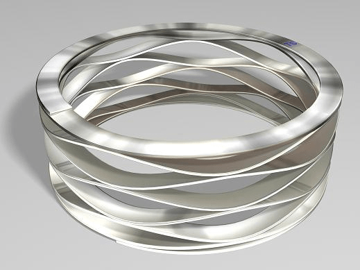
how about a collar and a thin wave washer. And tighten up the thrust plate up front with a torrington bearing, like Milodon gear drive setup. That cam wont walk anymore
left15be203c5f373419c808f08543dfaba20.png


I always thought timing off a chain and a helical gear was the most involved piece of engineering on a post was V8. many variables....how about just a high/low VR off the convertor/flywheel with a simple pickup at trans inspection plate. Put 4 tabs on the convertor (convertor bolts if they were symetrical) and run the pickup off the inspection plate. put another single tab inboard of those and pick it up with a second VR that switches something high, then low on each revolution, like an on/off transistor. the cam signal would sense whenever the transistor went high, ie. every 2nd revolution. No more sloppy distributor signal. Not an EE but I bet Kit could decipher my theory. Kit, check out the Jeep "distributor" (CPS) cover, it has no terminals like what you are looking for
large.JPG
 
Last edited:
Pishta,
Good you are thinking about this. Here is the desired sensor signals. Click to enlarge.
TAB_CID1K.PNG

The lower is CAM up for 4 down for 4. The middle is the tab wheel up for 50 degrees, down for 40 degrees. Timing advance occurs in the 40 degree section. Both signals are locked on the distributor shaft, so turning distributor for base timing both stay in sync. The upper trace is 2-strike ignition at 1000 RPM with only a few degrees of advance. The CID (cylinder identification) is a hall sensor in a standard 1992-1997 Dodge 5.2L distributor. The tab sensor is optical, LED on side photo transistor on other. Signal is high when tab blocks light, goes low when open. Where the edges occur are used by the ECU to control timing, they are regerence points.

VR sensors only generate voltage for change in flux. Greater change of flux with respect to time, greater the voltage. If metal is in front of sensor and zero speed, voltage is zero. If metal is in front and moving, but same thickness, flux does not change.. zero voltage. Here is a scope view of VR signal from Mopar electronic distributor.
IMG_0593 (800x578).jpg

The upper wave is the VR signal with engine turning about 3300 RPM. The place near the middle where there is a sharp slow from the low peak to high peak is where the tooth on the reluctor is passing the pickup. It passes zero when aligned. The trigger point is on the way up. Notice the amplitude of the second pulse is less than the prior one on the left, that is typical of run out. Amplitudes often vary much more and change timing trigger points. The trigger points vary with voltage thresholds of various ignition modules. A VR sensor does not generate digital high and low signals without significant analog circuit.

Here is a VR signal at about 300 RPM, notice how the amplitude is less.
IMG_0590 (800x661).jpg

The amplitude is about 6V pk-pk, the one above is about 35V pk-pk.

Here is the picture of the flex plate on rear of my 273.
IMG_0684 (800x600).jpg

I was thinking it going to be possible to use the spokes and trigger with a Hall sensor. The oil pan prohibits use of a circular threaded sensor. The flex plate is quite close to inspection plate. There is not enough room for tabs, mounting sensor and having adjustment room for base timing would be very difficult. The spokes of the flex plate would not result is a clean and sharp trigger. The trigger needs to be similar to the tab wheel, a clear and sharp trigger. The spokes also have openings, so they would generate additional signals. After markets plates are often solid, and designs changed over years, so I gave up on the rear timing sensor.

So rear sensing has complications, sensor placement, trigger targets, and the difficulty for base timing adjustments. The distributor option is plug and play, easy to static time and adjust, universal in application.
 
I have been making significant progress on the system. Much of the work involves changes in the design, for ease of manufacture. Here is a view of the proposed board and components. I am also investigating enclosures for the unit. There are molded sealed connector boxes available from Deutsch and Cinch.

COPsmt.png

EEC_325X4b.jpg
DTM13_12PA-12PB-R008.jpg
 
After much work designing, I thought the weather is nice, why not put the revised timing sensor prototype on the Barracuda and go for a drive. I did that and it worked! Starting is acceptable, it fires off in one engine revolution or less. Installation is easy, two wires, ignition power and ground, the rest is done in the harness. The base timing is accurately set using static method of setting crank at desired base timing and set specific tab wheel index to sensor slot, using normal rotation of distributor body, then tighten lock bolt.
20161020_101800.jpg

The U2 on the green circuit board shows the timing sensor, the tape on the tab wheel, indicates the tab edge to align with sensing slot as shown.
20161020_102404.jpg

I used a standard cap, unable to by a tower-less cap at auto parts store. Note the distributor is short, and without vacuum pod, it is easily rotated 360 degrees. "Ready to run" and other distributors are hard to fit on this 66, with A/C, oil pressure sender, and kick-down pars nearby. The newer Jeeps have such a cap, but my limited searching suggests it is only available in complete CAM sensor module including body and other parts that cannot be used on this system. Caplugs will be used to cover unused tower terminals, much easier than cutting off and resealing...

The ignition coils are mounted on valve covers, plug wires straight down to plugs, hard to mess up. I am using an old cut down set of MSD wires that came on a purchased.

The RPM and Vacuum settings were derived from 2D from my old post here:Ignition Timing in 3D The timing maps work so well, and so similar to my Mallory Uni-Lite, I would not know the difference. I will need to dive a bunch more and see if there is any improvement possible. After that I will evaluate what can be done with 3D table.

I plan on doing more posts, but will split to a new thread, this one is a bit long. I hope to post a poll, and see if there is enough interest for me to continue development. The poll will include more detailed information about the system, and why electronic advance, direct fire, the sensing system and other features make this an excellent system, compared to other available products.
 
It has been busy around here, new grandbaby, new house, and catchup work on the farm due to cooler weather. I started to do some more layout and packaging work, but stopped that thinking I had better be 100% satisfied with the unit first. The last change of adding the phase sense in distributor reduced crank time when starting. The starting while quick, sometimes acted like timing advance was not well controlled. When cold on first start, it would be too advanced. By capturing reference signals, I determined that engine slowing due to compression, resulted in advance timing. That is something I worried about in 2003 when I built my engine management for 4 cylinder VW engines. I incorporated locked timing while cranking, but later removed it when found unnecessary. The higher compression V8 has more cylinders, so going to locked timing at sub idle speeds would be a great fix. I thought about it a couple days to figure out how to best add the feature to the COP system. I was pleased that the solution was simple, and it worked flawless, including the ability for multi-strike. I now feel 100% about the system, and plan to continue development into a product.
 
Necropost! Kit, the VR sensor (in Ford EDIS) uses the zero crossing to trigger the coil, it has no relation to the (RPM induced) magnitude of the pulse..? Id be a willing collaborator with a 273 V8 with a modded electronic distributor with 1 vane left for the cam position sensor. COP/CNP sounds fun. How about a 72-2 optical "shutter wheel" where the reluctor goes (36-1+36-1) under the cap with another VR/hall sensor for the 1 lone extended tooth for a cam pulse for sequential?
 
I have technical skills, but zero for running company, marketing ... My life now is full, helping raise a young grandson.

If someone has interest to buy the technology, it could happen. When read about problems with Sniper, FITech,MSD... they could all benefit from my technology.
 
Nothing quite like reaching nirvana - completely understand not wanting to take any time away from that. Congrats.

Agreed - I'm fighting FITech ignition shortcomings and avialable solutions aren't cheap or elegant.
 
-
Back
Top