Demon 408
Well-Known Member
I spent some of my time today documenting the recent upgrades that I made to the electrical system in the Demon. I moved the battery to the trunk, by-passed the ammeter and wired in a new clutch safety and by-pass switch. Majority of the parts came from MAD Electrical http://www.madelectrical.com/index.shtml and Summit Racing http://www.summitracing.com/. This thread should help others who are thinking about making these same upgrades.
Parts to move the battery to the trunk:
Summit Racing
- SUM-G1231-K: $124.95
MAD Electrical
- Trunk-mount helper kit: $60.00
- Start’m up kit (relay): $40.00
Parts for ammeter by-pass:
MAD Electrical
- Wire and fusible links: $25
Redline Gauge Works (optional)
- Convert stock ammeter to voltmeter: $140.00
Year One (optional)
- Engine Harness: $140.00
Parts to repair clutch safety switch and install by-pass switch:
Radio Shack
- Micro switch $3.00
- Toggle Switch: $3.00
Misc. parts:
Year One
- Harness Tape ¾”: $10.00
Summit Racing
- Painless Performance Powerbraid Wire Wrap 10ft. (2 each): $38.00
- Thermo-Tec Thermo Flex Aluminum Heat Shield Sleeve (Black) 36”: $17.00
NAPA
- Ground braid: $8.00
MAD Electrical
- Butt connectors, shrink tube: $14.00
- Wire crimp tool: $31.00
- Wire stripping tool: $27.00
Radio Shack
- Solder Gun, dual range: $30.00
Ace Hardware
- Large heat-shrink for the 1/0 gauge battery cable: $5.00
My parts and tools
- Propane torch
- Hand tools
- Shop manuals
- Wire ties
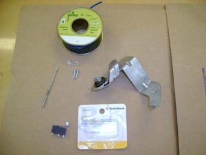
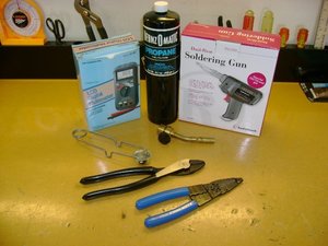
Now for the pictures. The first set will cover most of the misc. parts needed to do this job as well as my own schematic that documents all three upgrades:
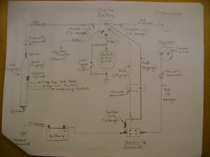
Here's my hand drawn schematic that shows all the upgrades that I made:
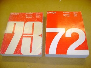
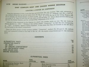
The 1973 Manual actually has a very detailed wiring schematic for the Dart.
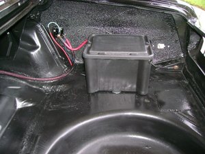
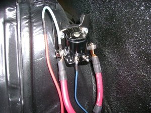
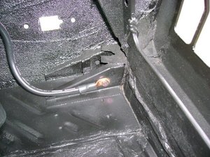
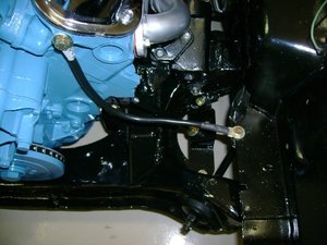
The next set of pictures documents moving the battery to the trunk:
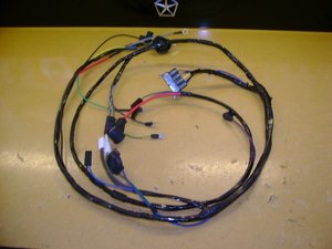
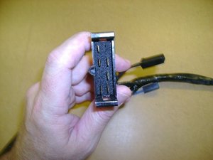
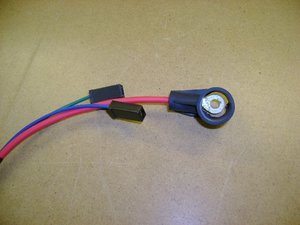
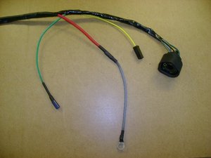
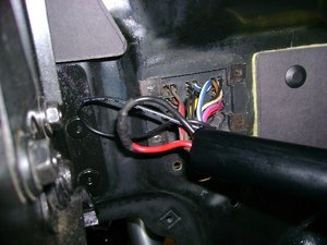
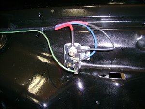
- 10 gauge red wire with fusible link provides 12 volts to dash area.
- 8 gauge red wire connects to battery 12 volts in trunk
- 14 gauge blue wire goes to the trunk to operate the "start'm up" solenoid.
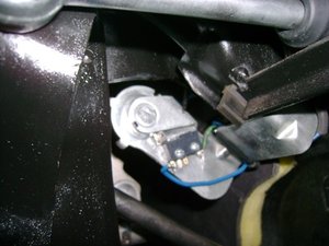
- 16 gauge green wire is the stock clutch safety switch ground wire.
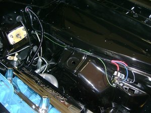
This shows my handy work using the harness wrap tape I bought from Year One.
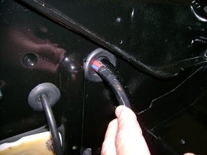
This shows how I used the stock grommet for the manual washers to route the wires from the starter relay and starter into the firewall. As a point of reference, that's the speedometer cable on the left.
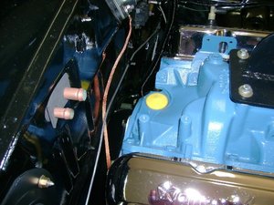
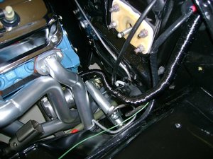
Starter wire route. Notice the use of the Thermo Tec heat shield and stock bracket to hold the starter cable.
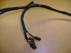
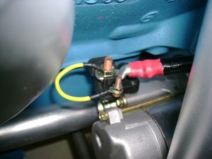
Jumper wire required on the starter when using the "start'm up" solenoid. (See MAD Electrical web site).
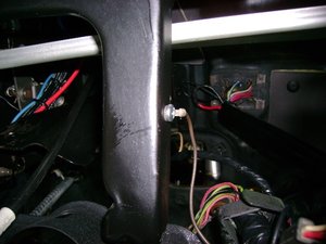
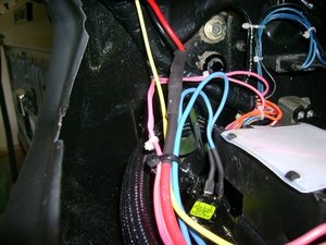
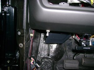
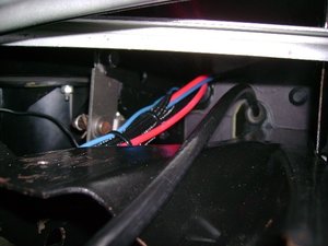
Wire route under the dash. As a point of reference, that's the speedometer cable on the right.
To be contined...


Parts to move the battery to the trunk:
Summit Racing
- SUM-G1231-K: $124.95
MAD Electrical
- Trunk-mount helper kit: $60.00
- Start’m up kit (relay): $40.00
Parts for ammeter by-pass:
MAD Electrical
- Wire and fusible links: $25
Redline Gauge Works (optional)
- Convert stock ammeter to voltmeter: $140.00
Year One (optional)
- Engine Harness: $140.00
Parts to repair clutch safety switch and install by-pass switch:
Radio Shack
- Micro switch $3.00
- Toggle Switch: $3.00
Misc. parts:
Year One
- Harness Tape ¾”: $10.00
Summit Racing
- Painless Performance Powerbraid Wire Wrap 10ft. (2 each): $38.00
- Thermo-Tec Thermo Flex Aluminum Heat Shield Sleeve (Black) 36”: $17.00
NAPA
- Ground braid: $8.00
MAD Electrical
- Butt connectors, shrink tube: $14.00
- Wire crimp tool: $31.00
- Wire stripping tool: $27.00
Radio Shack
- Solder Gun, dual range: $30.00
Ace Hardware
- Large heat-shrink for the 1/0 gauge battery cable: $5.00
My parts and tools
- Propane torch
- Hand tools
- Shop manuals
- Wire ties
Now for the pictures. The first set will cover most of the misc. parts needed to do this job as well as my own schematic that documents all three upgrades:
Here's my hand drawn schematic that shows all the upgrades that I made:


The 1973 Manual actually has a very detailed wiring schematic for the Dart.


The next set of pictures documents moving the battery to the trunk:
- 10 gauge red wire with fusible link provides 12 volts to dash area.
- 8 gauge red wire connects to battery 12 volts in trunk
- 14 gauge blue wire goes to the trunk to operate the "start'm up" solenoid.
- 16 gauge green wire is the stock clutch safety switch ground wire.

This shows my handy work using the harness wrap tape I bought from Year One.

This shows how I used the stock grommet for the manual washers to route the wires from the starter relay and starter into the firewall. As a point of reference, that's the speedometer cable on the left.

Starter wire route. Notice the use of the Thermo Tec heat shield and stock bracket to hold the starter cable.

Jumper wire required on the starter when using the "start'm up" solenoid. (See MAD Electrical web site).

Wire route under the dash. As a point of reference, that's the speedometer cable on the right.

To be contined...

