fixing am radio?

-
Rani,

Thanks for the schematic it brings back memories. The 1968 the schematic suggests a vacuum tube design was replaced with transistors. More modern designs replaced the audio coupling transformers by direct coupling transistors using emitter follower circuits.

Chrysler was one of the first with all transistor radios in 1955, my dad had one. It failed in the early 60's my uncle (a ham radio operator), repaired it with transistors taken from a pocket transistor radio. Watching my uncle do that, is what gave me the start in electronics.

Here is a 1955 Chrysler radio sales video.
[ame]http://youtu.be/RCPDFXKcbdc[/ame]
 
Interesting, Kit. The all-transistor radio must have been an extra-cost option which was more expensive than the standard tube radio.

I remember my 1960 Valiant had an all-transistor radio, which was its first year and was the standard radio that year. The sensitivity was rather poor.

My 1962 Valiant has a hybrid radio, which has good sensitivity.
 
Weirdest radios I've run across were the ones made for 1 or 2 years by GM, maybe others, which used "low voltage" B+ tubes.

Now the order of progress is like so:

In the early days, and up until real close to transistors, "tubes" had to have high voltage to provide the anode (plate) and screen, and in older designs, even bias voltages. So you had "A" for filament, "B" for anode/ screen, and "C" for bias. At first these were provided by batteries,

(advanced "tech," at the time:)

628x471.jpg


but in autos, later provided by the lovely VIBRATOR power supply. This is a chopper device used to provide "pseudo" AC so that a transformer would operate and step up voltage.

The guts of some vibrators. Basically a buzzer which opened and closed separate contacts as the thing vibrated back and forth

30708_6lo.jpg


A simple vibrator supply. Not all used vacuum tube rectifiers. Some were what is called "synchronous" which means they had two identical sets of contacts. As the primary contacts chopped up DC into "AC" for the transformer primary, the second set acted as rectifiers to "dechop" the "AC" output back to pulsing DC, then to be filtered. arcing. sparking. noisy. not reliable in today's parlance

VPS_58.jpg


THEN we developed "vibrator substitutes" which were transistor choppers to replace the vibrators for the high voltage, but still using "tubes" in the rest of the radio. These were used extensively in stuff like Motorola and GE "police" and other commercial radios

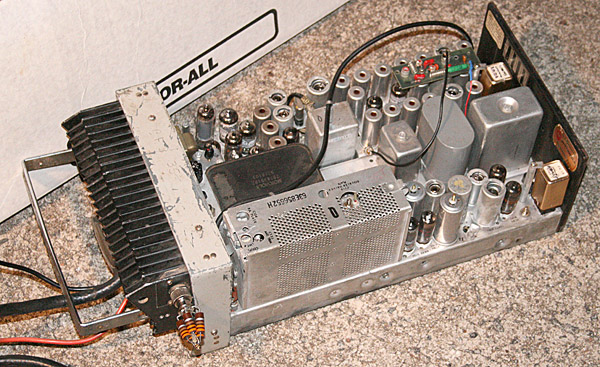
Old Motorola "T" power: The heat sink on the front is for the power supply transistors, the center chassis. The chassis nearest you is the transmitter strip, the shield at the left/ front being for RF power output stages. Just about everything in this radio is tubes except the T power unit.

070505-Motorola.jpg


In still higher power two way sets, sometimes a LOVELY device called a "dynamotor" is used. A "dynamo" is what people used to call what amount to a generator. A "dynamotor" is a "dynamo" and a motor constructed on the same armature. You feed this "black box" low voltage at high current, such as 6, 12, 24V, and out comes high voltage. In some cases VERY high voltage!!!

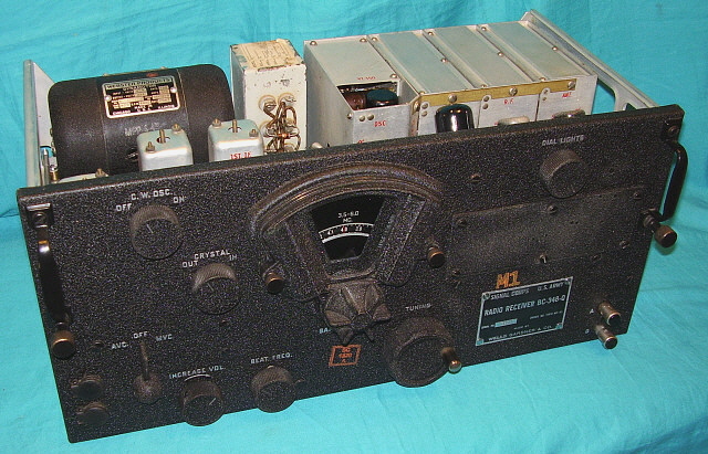
A BC-348 communications receiver, used is such stuff as B-17s and many other aircraft. The dynamotor, the black thing in the rear, was fed 28VDC and produced the B+ and other tube operating voltages

bc348out2.jpg


At about the same time, GM (maybe others) came up with a car radio based on special "tubes." These tubes require no high voltage for the tube anodes, operating right off the car's 12V power. However, the low voltage tubes cannot produce enough power to operate an audio output stage, so these radios would have one big power transistor for the audio output.

Low B+ tubes:

http://www.junkbox.com/electronics/lowvoltagetubes.shtml
 
A little late, but I'll throw my hat in the ring anyway.

A few tips: if it isn't working, check the power supply, if it is, check for broken solder joints, and use a pencil or non conductive prod and poke each piece to make sure there is no bad connection, and clean all the moving parts with pot cleaner.

Electronics are very linear, so it's not rocket science, you just need a methodical approach, and a schematic helps.

After you've fixed it up, another alternative is to stick the head unit in the glove box like I did, fits well, after you take the face off for security reasons, of course. :)

Enjoy!
 
This vintage late 40s - early 50s Collins 51J4 receiver has 17 tubes.
 

Attachments

  • 51J_front.jpg
    44.3 KB · Views: 449
  • 51J-4_top.jpg
    86.2 KB · Views: 433
  • 51J4_bottom.jpg
    126.3 KB · Views: 450
I used to own a 51J. Wish to 'ell I had it back. Used to own a 75A-4 at one time, too. But neither of those use either vibrators or dynamotors-- all 120V AC
 
The best advice so far is about the electrolytic capacitors. If I was going to start working on this I would be tempted to change every electrolytic capacitor in the unit. Unlike ceramic capacitors electrolytic's dry out with age. At that point the most common failure is they will short out, you can identify them by the +/- sign on them. Hook them up backwards and you will let the smoke out of them :burnout:. You also do not have to use the same one that you are taking out. Example if it is a can you can use a axial lead one if you can make it fit. Also value is not near as critical as with with ceramics. The Electrolytics are used for filtering and not tuning. Just make sure to use something close in value. If it a 50 mfd you could easily use something larger, if it rated at 25 volts just make sure it is at least 25 volts, higher is okay. What you are wanting to do is not rocket science but you should have a basic understanding of electronics. Before I spent a lot of time and or money to get a AM radio working I would take a look at these folks.
http://www.vintagecarradio.com/store/index.php?cPath=2 .

They look pretty close to original and for $150 plus you end up with a radio that looks old school and work new school, even with CD and MP3's. That is what I going to do with my 67 Dart.

67Dart273, I started before the T-power you showed, I started on twin V and dynamotor units. Oh for the good ol days. Not really I'll keep the modern conveyances.

Good luck with the repair, PM me if you need some help, I may be a little slow answering as I'm on the road a lot. :thumleft:
Bobby
 
The best advice so far is about the electrolytic capacitors. ................. I would take a look at these folks.
http://www.vintagecarradio.com/store/index.php?cPath=2 .

I don't see any reason to spend that kind of money. A car radio is not a show piece inside, so I see no reason to keep original looks, but newer caps are much smaller than old, and you can actually "gut" the old tin can electrolytics (with a little work) and slip new ones in from Digikey, Mouser, etc.

I do agree that caps are probably the no2 problem area after tubes, assuming a tube type radio.
 
Mopar offered Motorola AM radios, and my '62 Valiant has a Model 204, which was for the Valiant V-200. Motorola made 4 different types of AM radios for Plymouth and Lancer that year. They all used 3 tubes in the front end and 2 transistors in the audio stages, plus a transistorized power supply. I am referring to the Motorola service manuals, which are readily available.

The receiver didn't have any RF amp stage because I guess the AM stations were strong enough that it didn't need one. The antenna was fed right to the grid of a 12GA6, where it was converted to IF, then into a 12BL6 IF amp, and thence to a 12AE6A which did triple duty as a detector, AVC amp and AF amp. From there the weak audio signal went to a 2N573 germanium driver transistor and finally to a 2N176 germanium audio power amplifier and then to the speaker.

These radios used NPN-type transistors because a positive 12-volt power supply was available. (PNP transistors would have required a special negative power supply. In an NPN transistor, the voltage at the base controls the amount of current flow through the transistor, and it flows from the collector to the emitter. In a PNP transistor, the voltage at its base still controls amount of current flow, but it flows from the emitter to the collector.)

In my troubleshooting procedure above, I forgot to say you should check the "B+" power supply before going very far with the repair. In the case of my Model 204, after checking to make sure the transistorized power supply was producing plenty of voltage for the plates of the 3 tubes and that it was actually present at the plates, I would also check the power on the collectors of the 2N573 driver and the 2N176 audio power amp.
 
-
Back
Top