Frame connectors

-

65_valiant

Well-Known Member
Joined
May 23, 2010
Messages
399
Reaction score
14
Location
Wichita
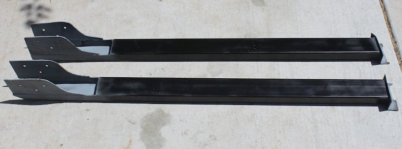
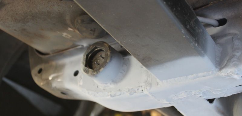
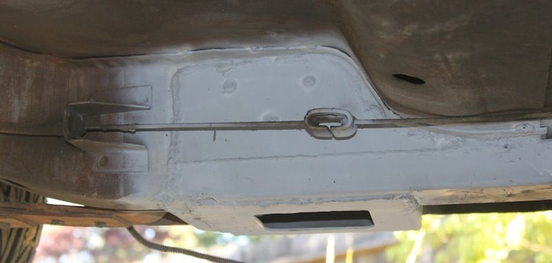
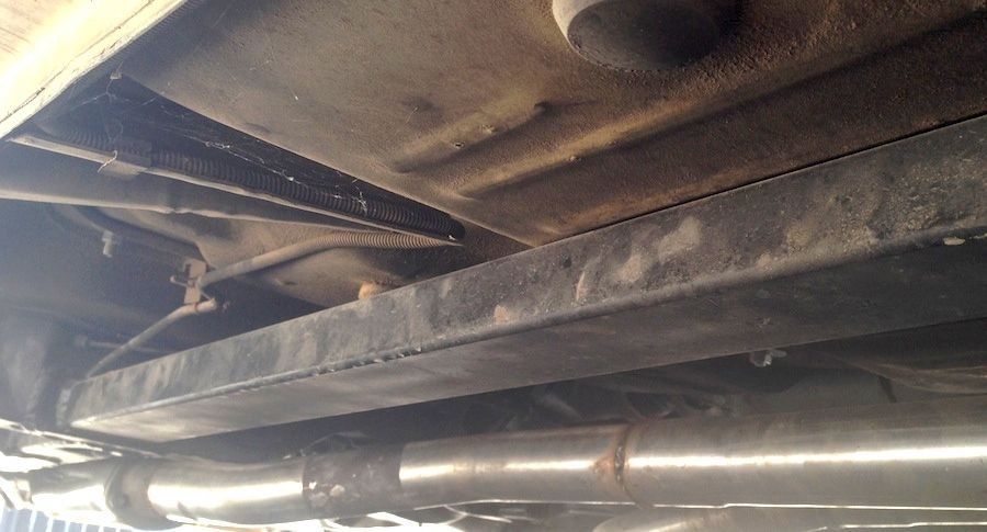
They really should be a required part if you are going to own one of these cars, so obviously they are definitely a planned part of the small build I'm attempting to get going over this next year or so.

My question is, are they enough to handle the torque of a 408? The stroker is a plan for the next 4-7 years, but if I need more rigidity than just the simple connecters will offer, I'd rather know sooner than later.

This wont be a drag strip car that's going to be ran harder than snot, BUT there will surely be some spirited nights on the town with it.
 
My question is, are they enough to handle the torque of a 408? The stroker is a plan for the next 4-7 years, but if I need more rigidity than just the simple connecters will offer, I'd rather know sooner than later.

I'm not sure about your comparison of frame connectors and simple connectors.
 
Simple frame connectors are those bolt 1x1 POS ones.
Decent frame connectors are at least 2x3 welded in and possibly even incororate the floor pan.

How's that for one end of the spectrum to the other. :D
 
If you are setting it up to hook, even on the street, get real sub frame connectors. 2x3 I would expect is a minimum.
 
1) Pictures of my subframe I fabed out of 2"x3"x 3/16" tube.
2+3) Jack holding subframe you can see the bar holding the gusset in place to be tacked in place.
4) Is the right side subframe
5) is a picture of the car floor. It's the backing plate for the subframe bolts. This plate is so the bolts won't pull through the floor. After everything was welded in place an bolted to the floor I welded the bolt heads to the plate.

Hope this helps you out.:glasses7:
 

Attachments

  • subframe.jpg
    13.2 KB · Views: 600
  • connecting frame #1.jpg
    14.8 KB · Views: 618
  • connecting frame #2.jpg
    14.3 KB · Views: 564
  • connecting frame #3.jpg
    15 KB · Views: 579
  • photo 3 (6).jpg
    55.4 KB · Views: 582
I got the US Tool connectors. They are not the square tubing that you have to cut the floor for some. But conform to the body.

http://store.uscartool.com/mopar-a-body-frame-connectors.html

I would never use this style ever again! More of a pain in the behind. I would go the square tube route next time. 2x3 3/16 wall or something and lay it flat so its wider in the horizontal plane. For 169 bucks you could buy alot of square tube.

The main problem i had with the "fitted to the floor" style was that it fit like a square peg in a round hole. I spent more time complaining and massaging that i could have just welded in the tube and moved on and still gain the strength i was after.

This is just my .02 and some change.
 
Fortunately the body shop is doing it for me, I work out of town and do not have time to do the body and paint. The car was a rusting shell when I bought it. I will do all the mechanical, but right now I don't. The body shop owner liked this type of connector, we talked about it before he started.

We all have different experiences with any product we buy.
 
It really depends on what kind of 408 if you build a mild 408 either choice would be fine. The engine in my car is a solid roller 408 with aluminum heads with some big time CNC porting I have the square tube connectors welded in and my car has still twisted to a point the filler in the sail panels is coming out and the passenger door needs adjusted.
 
I guess the question is;

(In a kit form/OOTB)

For the average guy, average street performer, mild build status.
What is a good general subframe connector?

For a heavy hitter type car, serious street strip or track only.
What is a excellent subframe connector for that seriously built engine?

Then, who has these or makes these?
 
I would never use this style ever again! More of a pain in the behind. I would go the square tube route next time. 2x3 3/16 wall or something and lay it flat so its wider in the horizontal plane. For 169 bucks you could buy alot of square tube.

The main problem i had with the "fitted to the floor" style was that it fit like a square peg in a round hole. I spent more time complaining and massaging that i could have just welded in the tube and moved on and still gain the strength i was after.

This is just my .02 and some change.

I installed these in my Duster a couple years ago. Like you said, big pain in the butt and required ALOT of fitting, trimming, and refitting along with a lot of up-side-down welding(unless you are lucky enough to have a rotisserie). All that said, I would use them again. I believe that incorporating the floor pan into the frame rails greatly increases the strength and makes a very clean and factory-appearing installation(if you're a decent welder). :burnout:
 
I installed these in my Duster a couple years ago. Like you said, big pain in the butt and required ALOT of fitting, trimming, and refitting along with a lot of up-side-down welding(unless you are lucky enough to have a rotisserie). All that said, I would use them again. I believe that incorporating the floor pan into the frame rails greatly increases the strength and makes a very clean and factory-appearing installation(if you're a decent welder). :burnout:

I would have to agree with you that those are probably the best as far as weight versus strength goes, and would be great if the car was already stripped for reconditioning or whatever and especially if the person had a rotisserie to do it.

3 inch wide tubing fits nicely over the existing subframe sections, so as an "add on" without having to take out the interior I think it comes in as a close second.
 
i used 1x3 scraps @ $1.50/lb. cut and fishmouthed the rear to slide over the frame rail and flanged the front to weld up against the torsion bar crossmember. I tacked it wherever it contacted the floor pan, about 5 areas. put it on equal jackstands first to square up your flexy 50 year old chassis first! When I jack the rear I get about 2 more inches out of the front now! it doesnt enter the floor. Im not putting down big launches but it does feel more solid.
 
Close...very close to what I'm doing.

I use 1x3, 1/8" wall tubing. I overlap the sides and bottom of the rear frame rail. Make sure you put holes in to allow the parking brake cable guide to bolt in on the right side! The front is bench welded to 1.5" angle stock, to attach to the tranny crossmember. It will add alot of stiffness.

Now; The body will twist under launch, along the axis of added frame connectors. Frame connectors do not add as much as you would think in this plane. the flex reduced is along the axis of the car, up and down in the middle of the body. The best way to confirm this is the "lift" test. If a car door opens and closes on the ground, but then won't when on the lift, the car is flexing. Frame connectors will fix this flex direction.

Picts to follow....
 
we added out riggers to the frame connectors
and cross members tied into loops
welded to the trans tunnel

where the outer pieces and the extra cross members meet
they are also short pieces of boxed tubing
welded in between them into the floor

002-6.jpg


011-4.jpg


002-5.jpg


034_zpsf717dcec.jpg

That is NICE!
 
I used 1.5" x 3" x .120" wall on my Duster. I overlapped the rear subframe pretty significantly, and in the front I tied it into the reinforcements for my torsion bar anchors. If I'd been thinking I would have used plates like draginmopars instead of just welding the separate reinforcing plates together.

The 1.5" x3" fits flush against the floor and the frame though, no need to cut anything like with 3x3, and nothing hangs down below the subframe like it can with 2x3. You can see in the last picture that you could weld them to the floor for quite a length if you wanted to.

IMG_4996_zps19e18495.jpg


IMG_5010_zps13f324a0.jpg


IMG_5012_zpse0044a73.jpg


IMG_1808_zps23307da1.jpg
 
we added out riggers to the frame connectors
and cross members tied into loops
welded to the trans tunnel

where the outer pieces and the extra cross members meet
they are also short pieces of boxed tubing
welded in between them into the floor

002-6.jpg


011-4.jpg


002-5.jpg


034_zpsf717dcec.jpg

That is very nice work! On a side note, you have no idea how long I stared at the second picture trying to figure what the hell kind of rear axle that was....till I realized that it was a transmission. Just a serious epic fail :banghead:
 
That is very nice work! On a side note, you have no idea how long I stared at the second picture trying to figure what the hell kind of rear axle that was....till I realized that it was a transmission. Just a serious epic fail :banghead:


LOL

Tail end of a 518

We had to raise and increase the width, of the trans tunnel
because we wanted a Trans shield
along with the 518 install
 
Simple frame connectors are those bolt 1x1 POS ones.


my reasoning on this is if your opinon of "Simple frame connectors" are a POS, why are they even in the equasion of thought?

this is what i am doing...
 

Attachments

  • val 19.jpg
    45 KB · Views: 283
  • val 26.jpg
    30.5 KB · Views: 292
-
Back
Top