Having charging issues

-

Andre68

Well-Known Member
Joined
Jul 2, 2013
Messages
572
Reaction score
5
Location
San Diego
Well my 68 Darts battery keeps dying. I know it's because it isn't getting charged, when I take it to oreillys there tester gives my battery alternator and starter a pass, but it always says that the voltage regulator has failed. Everytime. I changed it out right there in front of them and it still says it failed. Any ideas?

68 dodge dart 318 4 speed new battery alternator starter and pretty much everything electrical is new.
 
Please go search some of your other threads on this and post the links here so we can review. If possible, post a photo of your alternator

What are you using for an alternator and regulator? That is...................

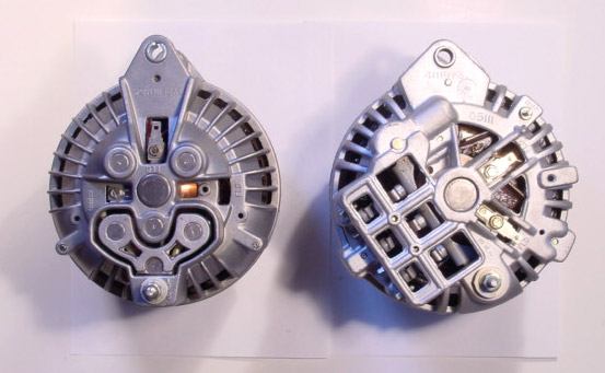
Is the alternator a "round" or "square" back?" How many field connector terminals does the alternator have and what did you do with them as far as hookup?

In the photo below, your original 68 looked something like the one on the left. You CAN and are BETTER OFF using a "squareback" on the right. But if you are still using the 69 / earlier regulator, you need to ground one of the two field terminals. Your original '68 only had one field connector

squareroundcomp.jpg


What regulator are you using, that is brand and part no?

What electrical testing have YOU done? Trusting "parts store" testers and people who operate them is no way to troubleshoot a car except for testing batteries (with a grain of sale) and in certain other situations.

In other words you are USUALLY far far better off doing some tests IN THE CAR under "operating" conditions. This allows you to troubleshoot wiring problems and so on, as well as components.
 
Thanks for the respond 67dart, pardon my newbie mistakes haha glad to have your help because your a pro!!

So after reading your post the first thing I did was go and take pictures of alternator and regulator. I then realized I that I did not have the alternator grounded, I thought to myself why is that? I looked up the wiring diagram because I didn't remember it showing a ground. I look at it now and realize that I missed the ground on the diagram. So as if right now my alternator is not grounded hahaha


Could that very much be the issue?
 
Those do not need to be grounded, they should be OK through the engine brackets. I've never grounded either the roundback or squareback

What is the brand and part no. of that regulator, and where did you get it? It does not look familiar from that photo.

===========================

Here's what you need to do..................determine if the alternator field has continuity

Do do that, disconnect your regulator, and hook your 12V test lamp to the two wires you unhooked from the regulator. Turn the key to "run". The light should go on. Go down and pull the field wire off the alternator. The light should go out.

Post back with results
 
I disconnected the wires and set the car to run, my test light did not light up, even did it with the car off and the same results.

The regulator I bought at the local oreillys. It's just there basic one. I believe master pro?
 
Next step...............

Clip your test lamp to the great bit output stud on the alternator. BE CAREFUL you do not short this to ground.

Make sure the lamp works by grounding "the other end" The lamp should light

Now, disconnect the alternator field wire. With one end of the test lamp hooked to the alternator stud, probe the other end to the alternator field terminal.

The lamp should light.

If not time to pull the alternator and check the brushes and field.
 
Alright well I had some trouble doing the first test, I must have done something wrong but I clipped the main stud I believe it's (BAT). I then probed the firewall and got no light. I then clipped the same stud, unplugged the field wire and probed that spot on the alternator and got a light.
 

Attachments

  • image.jpg
    54.8 KB · Views: 121
A multimeter would make trouble-shooting easier. With everything hooked back up, disconnect the FLD wire from the Vreg and measure resistance from the FLD wire to BATT-. If you measure infinity, the FLD wire is broken, the brushes are bad, or the 2nd brush is not getting grounded to the alternator case, or you don't have a good return path from alternator case to BATT-. If very low (<5 ohm) the wire is shorting to ground somewhere or the field is shorting to the case. The field resistance should be around 10 to 100 ohm (I am kind of guessing).

If OK above, when running verify that Vreg is applying a voltage across the two field terminals (brushes). ~12 V is "full output". You need an ammeter to measure the true output. The path to the ammeter in your dash could be bad (common) or the ammeter itself. Try the "Mad Bypass".
 
OK Andre, what you have verified is that the field is "probably good.

Now you need to chase it from the ignition switch to the field

The circuit path is...........

from ignition switch...........through the firewall

and branches off to feed BOTH ignition and regulator.

CHECK THAT your "IGN" wire feeding the regulator is "hot" with the key on.

You now know that the alternator field is probably good

So now, "backtrack"

Take your lamp, ground to the block (or multimeter) and hook the remaining probe to your IGN wire which went to the regulator. This should be "battery" voltage with the key in "run."

If not, find out why

If so, hook your green field wire up at the alternator and run the first check again

With the key in "run"

Hook one end of your lamp (or meter) to the IGN wire (originally blue)

CHECK that it has 12V to ground.

NOW move the GROUND connection of your lamp or meter to the green field wire. The lamp should light or you should get 12V on meter

If not, CHECK the green wire. It only goes one place---------from the regulator to the alternator field

If this check DOES show a circuit path,

take a clip lead and jumper the VR IGN and FIELD (blue to green) wires together. With the field hooked up (green) at the alternator and engine running, this should result in a "full charge" condition when RPM is increased.
 
Got some good news! I think haha well I started as you said 67dart and I traced the wire back to the firewall and I noticed that the one blue wire was kinda loose on the bulkhead. Pushed it in, decided to check the voltage regulator to see if it was getting power.

With the key in "run" I grounded to the firewall and put the test light to the voltage regulator and done I was getting light at both wires on the voltage regulator.

So is that problem solved? Loose wire on bulkhead?

Don't see why it wouldn't be good from here on out?
 

Attachments

  • image.jpg
    32.5 KB · Views: 97
So is that problem solved? Loose wire on bulkhead?
Don't see why it wouldn't be good from here on out?
Probably done, but if you didn't test that you had no voltage at Vreg before fixing the loose wire, can't be positive. A multimeter is much better than a test light. The FLD reading should be between 0 V (resting) and 12 V (max output) for your "one field wire" alternator.
 
-
Back
Top