High voltage Dart -67

-

Tommy Stark

Member
Joined
May 29, 2018
Messages
17
Reaction score
2
Location
Sweden
Hi there from Sweden
Cant get my head around my voltage problem
I've tried a new regulator and the bulkhead cut wire and a relay
Bought the car off an electrician so everything is a nightmare :D
It has a ready to run distributor and at one point in its life it's had an MSD system witch is off the hook now
The ignition key is some random fits all but really nothing and has
1. Starter
2. Ign
3. Battery
4. Acc
Is it possible to get a normal voltage on this setup or do I need an original ignition key or something else?
Thanks in advance
 
It depends on how a lot of things were wired. The use of relays etc.

OEM used 3 separate feeds to start the car.

Feed #1 (IGN 1) feeds the coil during run conditions thru the ballast resister.

Feed #2 (IGN 2)bypasses the ballast resister to feed full battery voltage to the coil


Feed #3 (Start) triggers the starter relay to connect the battery to the starter.

Some of the ballast resister and wiring might be redundant due to aftermarket ignition.
 
Am I missing what your voltage problem is? I see in the title it states high voltage.
Give some more details for members to chime in for troubleshooting ideas and solutions.
 
Am I missing what your voltage problem is? I see in the title it states high voltage.
Give some more details for members to chime in for troubleshooting ideas and solutions.
It's currently loading over 16 volts
I read about cutting one wire that goes thru the bulkhead and run it thru a relay so I did that and the voltage went around 15,5 volt so it's still too high
 
It depends on how a lot of things were wired. The use of relays etc.

OEM used 3 separate feeds to start the car.

Feed #1 (IGN 1) feeds the coil during run conditions thru the ballast resister.

Feed #2 (IGN 2)bypasses the ballast resister to feed full battery voltage to the coil


Feed #3 (Start) triggers the starter relay to connect the battery to the starter.

Some of the ballast resister and wiring might be redundant due to aftermarket ignition.
Any ideas on how to mount the wires to the ignition when I'm missing a separate feeder to ign1 or 2 or do I need a original ignition
 
It's currently loading over 16 volts
I read about cutting one wire that goes thru the bulkhead and run it thru a relay so I did that and the voltage went around 15,5 volt so it's still too high
You probably did the amp meter bypass? I did one a while back but no relay was required.
Do you have a diagram or a description of how you completed it?

Also, the voltage regulator and alternator are the only components that can cause high voltage.
Have you checked your meter with another?
 
You probably did the amp meter bypass? I did one a while back but no relay was required.
Do you have a diagram or a description of how you completed it?

Also, the voltage regulator and alternator are the only components that can cause high voltage.
Have you checked your meter with another?
The original amp meter doesent work
Have a separate volt meter
Cut the blue wire that went in the bulkhead
I believe both ing1 and 2 are put together on the ignition and I have a direct line between the alternator + to the battery + should that have anything to do whit it
 
Over 16 would SUGGEST (but not verify) that this is more than the usual voltage drop in the harness problem

The FIRST thing we need to know is what it is that you are running for an alternator/ regulator, AKA is this isolated field with the 70/ later Mopar regulator, or something else?

Is the regulator external or integrated in the alternator. PHOTOS may help, as it may not even be 'Murican, AKA Bosch or something.

IF your ignition switch does not have voltage drop across the switch itself, it can be made to work, and depending in the ignition system setup (I guess you said ready to run) but does it use a ballast resistor? Anyhow the switch can be made to work, but you may need a / some relays to relieve strain on the switch, etc

The BASICS of ANY alternator VR setup are this:

1...(Nowadays) you must have a good useable and COMPATIBLE battery. Some battery configurations like AGM etc / others like a little different "float" voltage but 16V is way out of the park. But the battery must not be sulfated, etc

2...Alternator and regulator must be compatible, AKA isolated field, grounded field, whatever, and of course with NO FAULTS in the field circuit

3....Regulator MUST be grounded to the extent that you have near ZERO volts between the regulator ground point (mounting, body) and the battery NEG post

4...Regulator power source and or sensing wire MUST have near zero volts difference between that point and battery POS post.

The TRICK is that voltage testing is often geared towards actual operating conditions AND you are testing for voltage drop in a circuit which is affected by current draw. THIS MEANS that you cannot willy nilly disconnect part of the circuit during testing because you will CHANGE these conditions, current, and therefore the drop

Again (photos are good) we need to know specifically what alternator and regulator you are running, to start with, and year model of the car will help as well
 
Last edited:
Over 16 would SUGGEST (but not verify) that this is more than the usual voltage drop in the harness problem

The FIRST thing we need to know is what it is that you are running for an alternator/ regulator, AKA is this isolated field with the 70/ later Mopar regulator, or something else?

Is the regulator external or integrated in the alternator. PHOTOS may help, as it may not even be 'Murican, AKA Bosch or something.

IF your ignition switch does not have voltage drop across the switch itself, it can be made to work, and depending in the ignition system setup (I guess you said ready to run) but does it use a ballast resistor? Anyhow the switch can be made to work, but you may need a / some relays to relieve strain on the switch, etc

The BASICS of ANY alternator VR setup are this:

1...(Nowadays) you must have a good useable and COMPATIBLE battery. Some battery configurations like AGM etc / others like a little different "float" voltage but 16V is way out of the park. But the battery must not be sulfated, etc

2...Alternator and regulator must be compatible, AKA isolated field, grounded field, whatever, and of course with NO FAULTS in the field circuit

3....Regulator MUST be grounded to the extent that you have near ZERO volts between the regulator ground point (mounting, body) and the battery NEG post

4...Regulator power source and or sensing wire MUST have near zero volts difference between that point and battery POS post.

The TRICK is that voltage testing is often geared towards actual operating conditions AND you are testing for voltage drop in a circuit which is affected by current draw. THIS MEANS that you cannot willy nilly disconnect part of the circuit during testing because you will CHANGE these conditions, current, and therefore the drop

Again (photos are good) we need to know specifically what alternator and regulator you are running, to start with, and year model of the car will help as well

20240707_150708.jpg


20240707_150324.jpg


20240707_150253.jpg


20240707_150242.jpg
 
OK you are using the pre 70 setup, which means that eliminates at least one aspect, which involves an improperly grounding field which causes full tilt charge

So do this:

Turn key to run, engine stopped. Stab one probe into the top of the battery POS post and the other post to the IGN terminal of the regulator. That is the "push on" flag terminal, not the screw terminal. Read that voltage which should be very low, the lower the better. if it is more than .3V (3/10 of 1 volt) you need to investigate voltage drop in the path from the batt to the VR

You may have already checked ground, but you want to stab one probe into the battery NEG post, and the other post "hard" into the VR mounting flange, being sure to stab through paint, corrosion, etc. This voltage also, is "lower the better," and zero is perfect

The TOTAL of any voltage read off these two tests is added to the VR set point. Meaning, if you have a VR which would otherwise be properly operating, at 14V and you measure 1.3V drop in these tests, then the battery would see a charge volt. of 15.3.

Next run the car at a fast idle, and with one probe on the battery NEG post, read the "high" or "key" side of the ballast, but since your wiring is not original I cannot tell for certain which side, so try both.


THAT reading will tell you the VR setpoint, which should be nominally 14V (13.8--14.2) If it is much off of that the VR is off, but you can also confirm that by connecting a temporary jumper from a good battery point (such as the starter relay stud--direct to the VR IGN terminal. See if that settles down the voltage

ALSO you should jumper across the ballast resistor if using an MSD. The MSD should have a large black (ground) and large red (direct to battery) and then a small red "trigger" or energizer wire which goes to your original coil + connection that is coming off the ballast to the coil

With the MSD ONLY connect the MSD proper wires to the coil DO NOT connect any other items to the coil, not a tach and not the radio supression capacitor.

The one big thing to remember is that the VR MUST be at exact battery ground and at exact battery + to properly sense and charge. The biggest issue is voltage drop in the system.

This is affected by CURRENT FLOW so battery state of charge and alternator loading can affect this problem
Read 1.35 volts on the regulator so made a few new connections on the ballast resistor and down to 0,35 now so guess I'll keep following those cables for more corrosion
 
We can see the crimps and terminals are medicore. Each of those will cause additional resistance.
Also the terminals have exposed conductors which may already be causeing problem because the insulation is not supported. This allows stress and movement right at the connection.
Such as seen here
1720367547622.png

Also - some of those wires are connected to the battery positive. The exposed terminals make it very easy to accidentally ground the battery. While the factroy provided a fusible link to minimize the damage, your previous owner probably did not. Be carefull if working with tools or wearing jewlery.

MSD trigger doesn't really care about the ballast resistor. You can jumper it as a belt and suspenders but its not normally an issue. MSD used to advise leaving it so one could go back to original ignition if needed in case of MSD failure.

Alternator in picture is a revised squareback. See "Identifying Alternators" thread for how the isolated field alternator works, and photos of how to wire them when using the grounded field regulator.
 
Last edited:
OK you are using the pre 70 setup, which means that eliminates at least one aspect, which involves an improperly grounding field which causes full tilt charge

So do this:

Turn key to run, engine stopped. Stab one probe into the top of the battery POS post and the other post to the IGN terminal of the regulator. That is the "push on" flag terminal, not the screw terminal. Read that voltage which should be very low, the lower the better. if it is more than .3V (3/10 of 1 volt) you need to investigate voltage drop in the path from the batt to the VR

You may have already checked ground, but you want to stab one probe into the battery NEG post, and the other post "hard" into the VR mounting flange, being sure to stab through paint, corrosion, etc. This voltage also, is "lower the better," and zero is perfect

The TOTAL of any voltage read off these two tests is added to the VR set point. Meaning, if you have a VR which would otherwise be properly operating, at 14V and you measure 1.3V drop in these tests, then the battery would see a charge volt. of 15.3.

Next run the car at a fast idle, and with one probe on the battery NEG post, read the "high" or "key" side of the ballast, but since your wiring is not original I cannot tell for certain which side, so try both.


THAT reading will tell you the VR setpoint, which should be nominally 14V (13.8--14.2) If it is much off of that the VR is off, but you can also confirm that by connecting a temporary jumper from a good battery point (such as the starter relay stud--direct to the VR IGN terminal. See if that settles down the voltage

ALSO you should jumper across the ballast resistor if using an MSD. The MSD should have a large black (ground) and large red (direct to battery) and then a small red "trigger" or energizer wire which goes to your original coil + connection that is coming off the ballast to the coil

With the MSD ONLY connect the MSD proper wires to the coil DO NOT connect any other items to the coil, not a tach and not the radio supression capacitor.

The one big thing to remember is that the VR MUST be at exact battery ground and at exact battery + to properly sense and charge. The biggest issue is voltage drop in the system.

This is affected by CURRENT FLOW so battery state of charge and alternator loading can affect this problem
Some new cables and a bunch of new cables lugs and it's working like a Rolex
Many thanks for steering me in the right direction of where to start
 
Obviously yours has been altered.
But this is how it originally was arranged

1967 Power Distribution, Ignition & Alternator circuits
1720369964967.png


How electricity flows
1720369578956.png


1720371209305.png
 
Yeah it was pretty simple but there's a hole lot off more bad cables into the bulk head. Gonna look around and try to order a new complete bulkhead if it's possible to find
Some folks simply eliminate the bulkhead connector and splice all the wires together.
 
We can see the crimps and terminals are medicore. Each of those will cause additional resistance.
Also the terminals have exposed conductors which may already be causeing problem because the insulation is not supported. This allows stress and movement right at the connection.
Such as seen here
View attachment 1716273004
Also - some of those wires are connected to the battery positive. The exposed terminals make it very easy to accidentally ground the battery. While the factroy provided a fusible link to minimize the damage, your previous owner probably did not. Be carefull if working with tools or wearing jewlery.

MSD trigger doesn't really care about the ballast resistor. You can jumper it as a belt and suspenders but its an issue. MSD used to advise leaving it so one could go back to original ignition if needed in case of MSD failure.

Alternator in picture is a revised squareback. See "Identifying Alternators" thread for how the isolated field alternator works, and photos of how to wire them when using the grounded field regulator.
Found a bunch more of them and they where full off corrosion so i made new cable lugs whit better isolation
Never thought it could lead to extra resistance but now I know
 
Found a bunch more of them and they where full off corrosion so i made new cable lugs whit better isolation
Never thought it could lead to extra resistance but now I know
It doesn't take much resistance to cause problems.
Another thing that many of us used to be too casual about is the wire routing and support. I know I used to think "why did the factory support the cables in so many places? It makes it difficult to wrench on whatever it was I was working on."

The resistance is good to understand. @67Dart273 was one of the people who got me to think about this and do the math.
A typical multimeter can only show major problems. It may measure 0 Ohms but there can still be enough resistance to cause problems.

Voltage = Current x Resistance. (V = I x R)

Given a connection with .06 Ohms resistance
Lets say say we turn on the ignition and 5 amps flows through that resistance.
5 amps x .06 Ohms = 0.3 Volts

What happens if the ignition and field circuit draw 10 amps?
10 amps x .06 Ohms = 0.6 Volts
Doesn't seem like much?
But what happens when more things are drawing current. It could be lights, wipers, and heater fan; or could be the first minutes of the battery recharging.
30 amps x .06 Ohms = 1.8 Volts

Two bad results are happening because of the big load even though it seemed like very little resistance.
Power = Current x Voltage. That power is energy converted to heat
The other bad thing is all the equipment recieves power at lower voltage or
if
the voltage regulator sees the voltage is low, it ups the alternator's output voltage. Some things may get high votlage and other get lower voltage power.

Chrysler accepted some voltage drop in the system, but not a full volt.
 
Last edited:
The other thing about resistance, is, that it CHANGES often, with load, IE heating up, arcing, etc, so the problem can get worse. That is why I try and encourage more use of voltage checks and depend less on resistance checks. Plus, ohmeters get less and less accurate as resistance decreases.

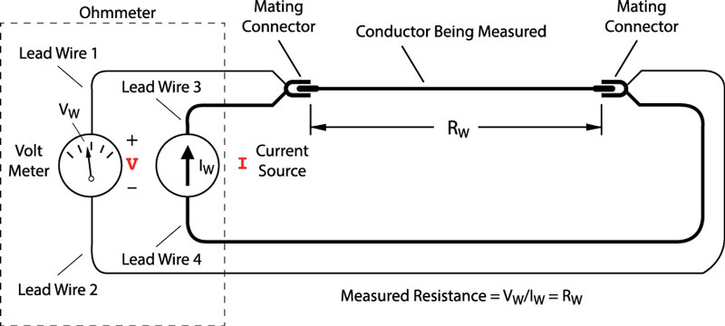
There is a procedure sometimes called "the 4 wire method" which is basically turning the test area into a shunt and running current through it, then measuring the voltage drop and calculating the resistance


So even though the end answer is R, the method is still "voltage drop" LOL
 
-
Back
Top