MAD Bypass Question

-

Bookmaker

Well-Known Member
Joined
Jan 8, 2015
Messages
162
Reaction score
50
Location
Moneta, VA
I am getting ready to do the MAD ammeter bypass on my 74 Duster using a direct wire with fusible link from the alternator post to the starter solenoid post. No big deal.

With regard to the ammeter itself, what would be the result if I leave the ammeter in the gauge cluster hooked up instead of disconnecting it and joining its two wires together to bypass the gauge?
 
You can do that without causing problems. The ammeter will no longer read correctly. There'll still be some current running through it, but nowhere near as much as before.

There's nothing wrong with the idea MAD discusses, but (as with other stuff on their site) their method has problems. You might want to read suggestions and discussion here and here.

(Also, people have successfully bought a cheap Sunpro voltmeter, torn it open,
and mounted the old ammeter face over it with excellent, clean
results. See here and
here.)
 
Thanks Dan. That is good info. I'm not concerned about the accuracy of the ammeter. For a 60A alternator, are two 10g wires with 50A fuses still a good idea or is it overkill? Thanks for your patience with my questions.
 
For a 60A alternator yes, I would do the 2× 10ga wires from alternator B+ to battery + with a fuse at each end of each wire.
 
In addition I would highly suggest that you do "Nachos' bulkhead parallel bypass" which is simply running 2 wires in the bulkhead halves straight thru for the main in/out circuits (in past the FL and out to the alt) instead of them being connected with the 2 pairs of brass terminals. take out the 4 terminals & drill out the bulkhead holes some so some wire will fit in there and solder in 2 lengths of wire, its hidden & takes care of a PROBLEM area. clean ALL terminals/connections.
 
For a 60A alternator yes, I would do the 2× 10ga wires from alternator B+ to battery + with a fuse at each end of each wire.

Dan, you look like you're havin too much dang fun in your signature picture. lol

Merry Christmas.
 
I mighta been…that was about six years ago. Don't own that car any more. Guess I ought to see about updating it.

Happy Christmas to all y'all, too.
 
OK, I've been reading through a bunch of old postings on this subject, and it seems that many have run an 8AWG wire with a 12AWG fusible link from the alternator directly to the battery terminal on the starter solenoid - essentially running parallel wth the stock bulkhead wiring as I had proposed in my first post in this thread. I haven't seen where anyone is running the 2-wire/4-fuse setup that Dan proposed. I don't mind doing it that way if that is the best way to go.

Q: Is the 8AWG wire with a 12AWG fusible link really insufficient? What is the risk?

Q: If I am taking load off of the bulkhead connectors by running a parallel bypass, how then is the bulkhead still a problem (assuming it is in good condition)?

I will also be adding Crackedback's headlight relay harness. My goal is to reduce the load on the stock wiring. I prefer not to cut/splice any of the stock wiring if possible. I just want to eliminate the weaknesses in a manner that is safe.
 
OK, I've been reading through a bunch of old postings on this subject, and it seems that many have run an 8AWG wire with a 12AWG fusible link from the alternator directly to the battery terminal on the starter solenoid - essentially running parallel wth the stock bulkhead wiring as I had proposed in my first post in this thread. I haven't seen where anyone is running the 2-wire/4-fuse setup that Dan proposed. I don't mind doing it that way if that is the best way to go.

Q: Is the 8AWG wire with a 12AWG fusible link really insufficient? What is the risk?
It depends on the load. The load in your scenario is the current needed to maintain the battery. Unless your trying to charge a dead battery with the alt or running battery power only, the highest load it normally sees is at start up. For reference, a '67 A-body, the factory wiring was just 12 gage on the alt side and 10 ga on the battery side of the ammeter. These carried almost all the loads placed on the Battery and alternator (almost because starter motor and horns have direct wires).
Q: If I am taking load off of the bulkhead connectors by running a parallel bypass, how then is the bulkhead still a problem (assuming it is in good condition)?
Everything else is still drawing from the main junction inside. However, with a headlight relay system installed, another big load has been removed from that junction, and therefore the bulkhead.
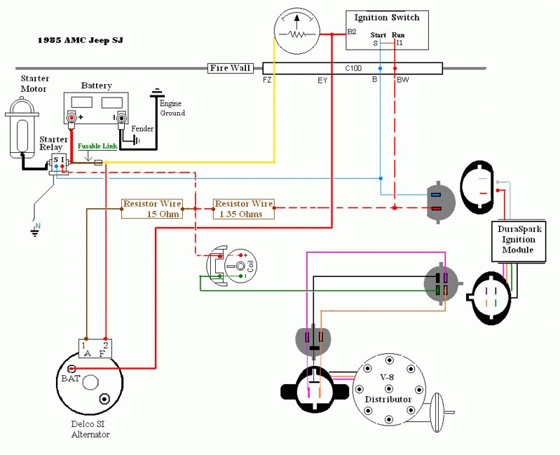
Here's a diagram I recently made for my jeep, which is similar. Even though the connections are not drawn in, the junction between the ammeter and the ignition switch also feeds the headlights, ignition, and everything in the fusebox! So each of the changes you are proposing takes a load off of the connections. You can see that if you weren't adding the direct wire from the alt to the battery, then it's best to hook the headlight system to the alternator output.
 
Nice diagram, Mattax. How did you produce that? Is there an on-line program for it?
 
Thanks. Credit must go in part to the original creator of the template. I was going to include that info but the IFSJA website where I first posted was down temporarily.

I actually started by using the example rather than blank template. Go down this page at Jeepforum, Wiring 101 to the bottom of post #3 for the links to the templates. It's actually hosted at a website called Civilian Jeep, but Civilian Jeep doesn't index it. go figure. I used MS Paint which works well with gifs. The mid 80s AMC wiring diagrams are almost impossible to follow; makes one appreciate how clear the Chrysler and even older AMC diagrams were.

To modify it for our Chrysler systems will need to change a bit more. The '85 SJ's used a GM alternator with regulator inside the case. The starter is Ford type with the starter relay directly in the circuit with the starter. In contrast Chrysler starter relays are only in the circuit to the starter solenoid. In that arrangement the heavy plus cable goes directly to the starter.

Jeep SJ Diagram notes:
The dashed red line is a wire with red insulation and white trace. The Alternator is actually grounded to the engine even though I didn't put a ground symbol on it. The switch to ground with an N next to it is the Neutral Safety Switch.
The junction between the Ammeter and B2 also feeds the Headlights and other circuits that don't require a key ON to work (like the Dome light). The ones that do need key 'on' are fed through the ignition switch, but I didn't show that either.

PS. You should be able to download and modify my drawing. If not, let me know and I'll see what permissions I need to change at Flcker
PSS The wires to and from the SJ's Ammeter are 10 gage with a 14 ga fusible link (according to the factory diagram anyway). The highest output alternators from the factory that year was an 85 Amp for fleet, 78 Amp for individuals. In '87 an optional 94 Amp was available.
 
OK, I've been reading through a bunch of old postings on this subject, and it seems that many have run an 8AWG wire with a 12AWG fusible link from the alternator directly to the battery terminal on the starter solenoid

That works, too, but it's a longer run of more difficult-to-work-with (8ga) cable, and fuselinks are much more of a pain to service than fuses. Here's someone who wound up glad he did it the way I suggested.

I will also be adding Crackedback's headlight relay harness.

Good upgrade.
 
For a 60A alternator yes, I would do the 2× 10ga wires from alternator B+ to battery + with a fuse at each end of each wire.

Dan,
Why two 10ga in parrallel? Why not one 7ga with 100A fuses? Although, I guess you'd have to use 6ga; 7ga is probably uncommon. Is it just that the 10ga is easier to work with?

Bob
 
An aside, for "you guys" that like "one wire" alternators, you need to REALLY oversize the charge wire to the battery. Delco used to have a chart. Seems to me for a 60-80A "one wire" no6 is not "too large."

The biggest reason for this is that one wire setups "sense" through the charge line, so more drop there means less system / battery voltage under heavy load.
 
Looking at doing the ammeter bypass/bulkhead terminal elimination, and possibly the headlight relay. Anybody got anymore good advice,links, pics, or things to avoid?
Maybe tips to consolidate all the different connections feeding off the starter relay?

I recently added electric fans and noticed the amp guauge starting to cook Christmas Eve.
 
Where you pull power on the old mopars is important.

Headlights since they are rarely on with engine off, alternator. Fans, power top and some other accessories, might be better at the starter realy or B+. Depends on whether you run those items with engine on or off. If you have a lot of heavy pulls, running a distribution stud, attach charge line and run a heavy gauge line from B+ is decent approach. Not factory, but would be better than the starter relay.

The wire around, upsize it from the standard wire. The ones I put together 8ga with a fusible link. The larger the wire from alt to battery the better to a point. 6ga would be about as big as you may need based on amp draw.

Lots of ways to skin a cat.
 
Thanks Crackedback, can you post a link to your headlight relay setup?

TXDart and I were even talking about maybe adding another fuseblock up front.

I have hooked to the starter relay-

Electric vacuum pump
Fans
MSD 6AL
Starter

It's getting a little crowded.

 
To answer the OP, no problem leaving the ammeter wired as is. You don't buy much by connecting the two wires on one terminal other than in some clusters those terminals are iffy (corroded, can loosen). The main goal is to give a direct underhood path from ALT to BATT+ to keep large charging currents off the bulkhead connector.

The cleanest relay approach is to rewire with an underhood fuse/relay box from a newer car. I posted on that years ago "Modernized engine wiring ...". 67Dart273 did similar. I also posted a way to bypass large charging currents while leaving the ammeter active by use of a large diode pair, but beyond the understanding of most.
 
What method to the madness is best ?,,, its a matter of opinion. A box from another car ? Its labeling and wire colors are all wrong. I had to keep the next owner in mind when doing these mods. Reason being, I know who the next owner is.
 
Couldanybody who's done this post pics of the ammeter bypass or how they routed the alternator to battery lines, or any other mods? ...or post some links to good illustrations?
Just looking for some good ideas.
 
... pics of the ammeter bypass or how they routed the alternator to battery lines, or any other mods? ...
Simply run a thick wire from the big stud on the alternator to the big stud on your starter relay. The factory wire is 12 awg (my 60's Mopars) so use thicker (at least 8 awg). Smart to run it in a sheath (SPC Tech PVC tubing or split loom).

If your battery is closer or easier, run the wire to BATT+ instead. Either way, you still have the factory wire (12 awg my cars) between BATT+ and starter relay, so smart to up-size that too.

Other ideas - put as many under-hood loads as possible on relays (powered from BATT+ via fuse). Many put headlamps on relays. Mandatory for an electric radiator fan. The factory already put the horn and starter on relays. If adding big cabin loads (high amp stereo?), you might do the "fleet bypass" where you hard-wire the ALT and BATT circuits rather than rely on the spade terminals in the bulkhead connector (commonly melt, unless 1963 or 1965).

If you really want to get fancy, read my post
http://www.forabodiesonly.com/mopar/showthread.php?t=176755&highlight="Modernized+Engine+Wiring"
but you won't be able to do everything there unless you are an electrical tech or engineer. Also search for posts by 67Dart273 who did similar.
 
You can do that without causing problems. The ammeter will no longer read correctly. There'll still be some current running through it, but nowhere near as much as before.

There's nothing wrong with the idea MAD discusses, but (as with other stuff on their site) their method has problems. You might want to read suggestions and discussion here and here.

(Also, people have successfully bought a cheap Sunpro voltmeter, torn it open,
and mounted the old ammeter face over it with excellent, clean
results. See here and
here.)

Dan I read your post that you linked on the slant 6 forum, and have a question that I hope you can clear up. When you pit the two 10 gauge wires from the alternator to the positive battery terminal do you remove the factory wire or leave it in place? Also does running these two wires in any way mess up the voltage regulator since it seems to be bypassing it? I am not too familiar with the wiring diagrams for these cars so please forgive my ignorance.
 
-
Back
Top