Old school timing light

-

iw378

Well-Known Member
Joined
Sep 15, 2013
Messages
794
Reaction score
112
Location
Suisun City, Ca
Anyways I couldn't help myself being the tool hoarder I am.
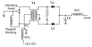
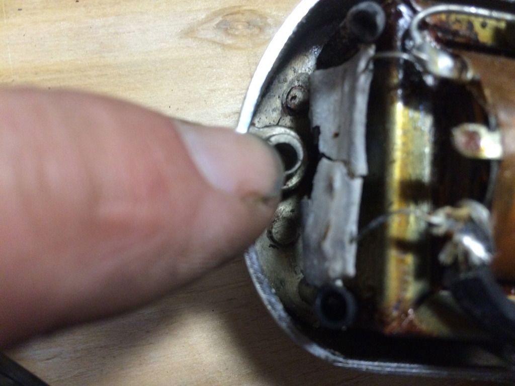
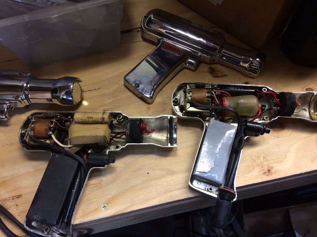
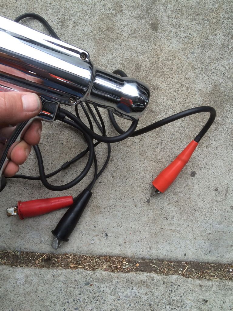
I have always wanted one of these lights and this one looked to be in great shape with the box. 10 bucks. It does not work. I put a steel probe through the number one spark plug boot to hook up the sensor wire. When I pull the trigger I can hear something working inside but the light will not flash. Is there anyone that repairs these. Prolly not worth it but I want it to work just because.. LOL
IMG_0334_zpsiffxqsky.jpg
 
Some of those had a "vibrator" and NO I AM NOT $h*tting you, LOL

They either have a solid state oscillator, or an old fashioned vibrator to produce pulsating DC voltage which is then stepped up for high voltage to fire the lamp

Hard to say.......could be a power supply problem or a bad flash tube. You can buy flash tubes here and there, not necessarily "shaped" the same as what's in there

Some old vibrators torn apart........These were used, EG in car radios before about 1960 when transistors gained some ground.

An old heathkit vibrator 12V supply, would have been used with some sort of amateur radio "mobile" equipment

vibrator_power_supply_gp_11_779740.jpg


A very simple vibrator power supply. From the transformer to the right, this is a conventional diode rectifier / filter. If you were to unhook the vibrator from the left side, you could feed low voltage AC into the left side of the transformer, and get "pretty much" the same output.

HOW it works, looking at the left side of the transformer. The vibrator is essentially a double -throw relay so to speak. The contacts of the "relay" are wired in series with the magnet coil. So when you hook it up, the magnet tosses the armature over to one side, and the contact unhooks the power "from itself." This causes the armature to flop back again, ---closing the contact again, hooking power back up to the magnet, and throws the armature back as it did before. This settles down in a cycle. A DC buzzer OR A HORN works exactly the same way.

The contacts then, make and break as the thing "vibrates," making an on/ off pulsing that simulates AC

smps-fig1.gif


30708_6lo.jpg
 
Okay Dell I just got another one that was sold as "working" It does not work either. I opened it up to see what was going on and I found this.
IMG_0358_zpsxr8takpu.jpg

On the first timing light in question when hooked up to 12 volts I can feel the vibrator clicking on and off as I squeeze the trigger but the bulb does not flash. On the one with the cracked resistor there is no such thing. is there a way to test the bulbs with 12 volt power ? I think I should be able to make one work with parts from two
IMG_0359_zpswmsvzvxk.jpg
 
Both of those appear to have the vibrator for power.

Do they make noise, "hummmm" when hooked up and triggered?

Common problems........(in no particular order)

1.....Good power supply but bad flash tube. Hook up the 12V and trigger it, see if it hums. BE CAREFUL Hook your multimeter up on the highest voltage setting, to the end wires of the capacitor. With the thing triggered, you should find several hundred volts DC there, perhaps 350 or so. If so, probably bad flash tube...........if not......

2.....Problems in high voltage power supply.

2A.. If the vibrator does not vibrate, it's probably bad, or might be bad transformer, switch or connections.

2B..If the vibrator hums but there is no high voltage at the cap, might still be bad vibrator contacts.

2C..I cannot tell if this is a "self rectifying" (in the vibrator circuit or "synchronus") or whether there is one or two rectifier diodes in the circuit. If the latter might be a bad diode, or even bad transformer.

Depending on how deep you want to get into these, there are probably DIY circuits "on the net" for transistor supplies to replace the eintire vibrator supply. It's also possible that you might "luck out" and there are different components bad in each one, "morph" the two into one working unit.

EDIT Found this which seems similar

https://www.google.com/patents/US2959711

https://patentimages.storage.googleapis.com/pages/US2959711-0.png

Another approach might be to find a newer / cheaper plastic working light and install the guts in that case.
 
If you hear the buzz, that is good, the vibrator is mechanically working. The contacts could be worn, but the most likely failure due to age would be the capacitors. I am guessing the high voltage capacitor used for the flash energy is in the handle, that might be C1 in 67Dart273 schematic. There are two pins on the tube, they get the 300 to 400V DC. The voltage is boosted by the center-taped transformer, rectified and stored in C1. The plug voltage goes to the winding on the tube, it ionized the xenon gas, the flash discharge drains the capacitor. The vibratory action switches 12V in an alternating manner to boost via transformer between spark events ....
The capacitor is likely an electrolytic, that means it was liquid between the plates. If the electrolyte dries out, aluminum foil plates corrode or short the capacitor fails. Much smaller replacement and better capacitors can be found today. My guess would be to use a 450 VDC with a capacitance of 1 to 5 uF. That will make a short flash. Many circuits may show more, but those are to light a room for taking pictures.

The bulbs do wear out but they often look as if metal plated inside with a dark cast first.
 
Cool old lights. I still have my Dads old Craftsman light we bought him in the mid 70s. it doesn't hum but emits a low volume high pitched squeal, I guess that's the best way to describe it. It still works fine but will give you a little tickle if you're leaning on the car.
 
That Sears light has transistors in a circuit to alternate the driving of the transformer. About 45 years ago I built my own for about $10, using RadioShack parts. Back at that time there were cheap neon lights, I used the focus lens from a broken one of those.
 
"About 45 years ago I built my own for about $10..'" Kit

About 3 months ago, I bought a new one for $7. Sorry Kit, had to throw that on in there ;-). I think it worked once, but thats all I need it for prior to a smog check! I have since bought a decent dial back one that actually works. You sure those aren't Buck Rogers movie props?
 
This ad is for an Allied Radio "Knight Kit" tach, the first kit I ever assembled, around 1966

34dflvn.jpg


You won't BELIEVE how you calibrate it. The kit supplied a large value resistor, which you hooked up in series with 120V line voltage to the trigger circuit. You use 60 Hz line power to set the tach. I'd have to take a minute to figure out just what that works out to for a V8
 
Those multivibrators used to be used in the 50's car radios. When they had no B+ voltage (high voltage for the plates of the vacuum tubes) it was typically the multivibrator. These worked pretty much like the points in a car. It used a coil and capacitor along with the multivibrator to produce the B+ voltage and just like the points in a car they pit or get dirty. I used to use a pair of diaginals take the can off of the multivibrator and I would file the points and adjust the gap to achieve the proper voltage, maybe you will be able to do the same here.
 
This ad is for an Allied Radio "Knight Kit" tach, the first kit I ever assembled, around 1966

34dflvn.jpg


You won't BELIEVE how you calibrate it. The kit supplied a large value resistor, which you hooked up in series with 120V line voltage to the trigger circuit. You use 60 Hz line power to set the tach. I'd have to take a minute to figure out just what that works out to for a V8


OUCH!!!!!!! That would be a lawsuit waiting to happen in 2015!

And...$25.00 was a lot of money in 1966!!
 
-
Back
Top