Ron Francis Wiring help 2 !

-

Frank1970

Member
Joined
Feb 27, 2016
Messages
18
Reaction score
0
Location
New York
Hello All,

This is my first post here, I have a 70 charger, iam posting here because of an old thread, see below. Also i cannot get on for B bodies at work! Its blocked but A bodies is not!

Ive been asking around for a while in regards to IGN 2 lead from the ign switch and getting mixed answers and confusion.

I do not have any original harnesses, using only Ron Francis with regards to start and run. Iam using an MSD all in one distrubutor so no ballast. Also using a one wire ALT - powermaster.

I see this old post is 5 years old and iam still getting mixed info as to what to do with IGN 1 and IGN 2. RF techs say just tie them together so they feed their one ign wire.
I tried this, car cranks well and appears to run, as soon as release the key to fall back into run position, crank sound comes back. It sounds like the switch is confused.

What id like to try is just running IGN 2 straight to the coil, and IGN 1 to the one ign lead from the fuse box. I think this makes sense to me.

This would mean i would have a coil feed lead from the fuse box, ign 2 and MSD distributor feed on the POS coil. I have not tried this yet maybe tomorrow or monday. If this does not work then iam confused!

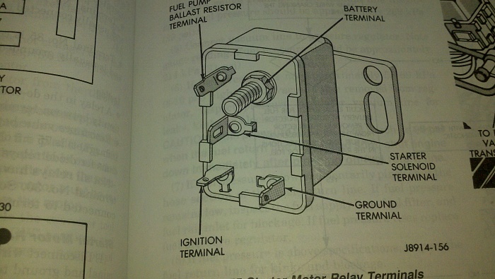
They also suggest in addition to tying IGN 1 and 2 together, to use a diode lead from the I side of the starter relay to the POS coil. If they are suggesting this then is suspect that single IGN lead is not for start and run together, just run. This tells me that their kit requires a second lead to the coil during start to supply 12V during start.

I hope i explained myself and made some sense. But this is amazing that this issue was discussed 5 years ago and RF team cannot give a detailed explanation as to the correct way to run.

I dont want to rely on a doide, worring if that will ever fail.

Thanks!


http://www.forabodiesonly.com/mopar/showthread.php?t=158859
 
No, they should be tied together. Either something is mis-wired, or you have a bad ignition switch.

There are only so many "things" with the switch, but here is the general

1...you have one big main battery supply TO the switch

You have ACC which is hot both in "run" and ACC. Unless this is wired wrong, not the issue

3...You have "Ign 1" which is ONLY hot in run

4...you have "Ign 2" which is ONLY hot in "start" and originally bypassed the ballast resistor. The reason you must tie it to IGN1 is because IGN 1 goes cold in start

5..You have the START terminal which SHOULD only feed to the start relay (yellow). This may be cross wired, or you may have a problem "in the switch."

There ARE alternative ways around this problem

1....You can use the later Jeep start relay which has an extra contact and can be used to replicate the IGN2 function

182185d1363835714t-1988-comanche-issue-starter-relay-diagram.jpg


2....You can parallel a second relay (Bosch) across the coil of the start relay so they come on together, and use the contacts to replicate IGN2

3....you can branch off the yellow "start" wire with an isolation diode to feed power to IGN1 during cranking.

===================================

"How to find" this problem?

I would try to figure if it's wiring, or ignition switch

Disconnect the ignition switch. Disconnect the "start" wire from the start relay. Check continuity from it to your IGN1. There should be none. (Infinity.) Check continuity from the start wire to ground. should be open. In other words the "start" wire should be one simple wire, going from the start terminal on the switch to the start terminal on the relay. With the switch and relay disconnected, that wire should go "nowhere."

Likewise, check your "IGN 2" wire. With the switch connector pulled loose, separate the IGN2 wherever it ties into the IGN1. This, again, should create one wire, separate, which goes nowhere. It should be infinity to ground and to other circuits.

Thanks, but you suggested in the last post from 5 years back to run IGN 2 straight to the coil. ITs sounds the same as running a diode, IF ign 2 is hot during start why cant that feed the coil? Ign 1 in run will take over and feed the coil via a coil feed from the fuse box.
 
The switch is brand new, yellow starter lead is attached to the right side of the starter relay (same side as passenger), the other side is the contact for the neutral safety switch.

I tried using both, only IGN 1 and only ign 2 - no run, well it sounded like it was about to run when both were together but once i released the key, it went back to crank.

AS far as i understand, when you turn the key this allows the BAT POS feed to feed the other wires in the switch based on the position - IGN 1, IGN2, ACC.

My thinking is once i the key is in start IGN 2 will feed the coil (connected directly), once in run IGN 1 will feed the fuse box which will feed their coil feed lead that runs from the box to the POS coil side.
 
I gave you the answer

Either it's mis wired

or the switch is bad (new does not mean functional)

You need to go through as I outlined and check continuity. Lots of us have done this. It does not matter where you tie 1 and 2 together, either "under the hood" or right at the switch.

A properly wired and properly working ignition switch isolates the IGN1 / IGN2 from the START contact. The three of them, in effect are three separate switches in one housing.

Oh, Ok i was looking for further explanation. What you said 5 years ago is very different than what you are saying, thats why i joined this site for further clarification.
 
What did I say 5 years ago that's different?

I don't know how to further explain this. There HAS been cases of bad ignition switches. Evidently they become "broken up" inside, and the contact pieces move around in there and do weird things.

Especially when you start with aftermarket harnesses, I have no idea how it actually might be wired.
 
What did I say 5 years ago that's different?

"send IGN 2 to the POS coil directly and be done with it" I put the old post in a link below on my first post. I didnt want to restart an old post, so i put a link in instead.
 
Test light ignition 1 and 2 wires separately for power in the respective key position. If all is good there, tie the two together and run a single wire to your coil + terminal.

If it doesn't test light, look for why in ignition switch, etc.
 
Test light ignition 1 and 2 wires separately for power in the respective key position. If all is good there, tie the two together and run a single wire to your coil + terminal.

If it doesn't test light, look for why in ignition switch, etc.


I get the point of tying the 2 together to connect to RF 1 ign feed wire. This says that that lead is hot in start and run. Coming out of the box is a coil feed - this then should also be hot in start and run. Then why would they also recommend using a diode connecting to the IGN side of the starter relay, pigtailed into the start lead from the IGN switch? It sounds like to me that i need a hot lead during start. I thought since IGN 2 is hot during start, why not run it directly to the + coil rather than using a doide lead.
 
GM Bias? How the heck should anyone that's works on mopars know what the RF techs are thinking. Why don't you ask them specifically why they want a diode in the ignition wires? It may shed light on the issue.

Mopars have three separate ignition circuits to fire each.
 
I dont know if iam explaining myself correctly. If that coil feed from the fuse box is hot during start and run, why would i need that diode lead from the relay?

At the switch if i tie IGN 1 and 2 together and connect them to the only IGN lead from the fuse box.. current goes to the fuse box, then i dont know where it goes after that, i assume it now feeds the coil feed wire. This would makes sense to me if that was all i needed to do, which is what i did. But now adding another 12V source during crank from the relay to the coil does not make sense if that coil feed is suppose to be hot in start and run.
 
I wired my Mustang with RF and you are correct, I needed to supply power to the distributer during crank. I used the stock mustang switch, they wanted me to use their aftermarket switch , which I believe provides crossover voltage during crank
 
GM Bias? How the heck should anyone that's works on mopars know what the RF techs are thinking. Why don't you ask them specifically why they want a diode in the ignition wires? It may shed light on the issue.

Mopars have three separate ignition circuits to fire each.

I asked them, no straight answer, i dont know how the fuse box is wired, no diagrams

I dont want to rely on a doide for a 12V source to my coil, if that failes on day, i get feed back to my relay!
 
I wired my Mustang with RF and you are correct, I needed to supply power to the distributer during crank. I used the stock mustang switch, they wanted me to use their aftermarket switch , which I believe provides crossover voltage during crank

RF never mentioned that! THanks
 
I wired my Mustang with RF and you are correct, I needed to supply power to the distributer during crank. I used the stock mustang switch, they wanted me to use their aftermarket switch , which I believe provides crossover voltage during crank

I think i have that power supply by using IGN 2 in my switch, but i cant get that confirmed by anyone, i have not tried it yet, i will be trying tomorrow AM!
 
"send IGN 2 to the POS coil directly and be done with it" I put the old post in a link below on my first post. I didnt want to restart an old post, so i put a link in instead.

Exactly the same thing electrically.

What you "had" in the old harness is.......

IGN1 went directly from the switch through the firewall to one end of the ballast.. The other end went to coil +. This is true both with points or Mopar breakerless

IGN2 went directly from the switch through the firewall to the coil+ end of the ballast. THAT WIRE so far as I know is not included in the Francis kit. You CAN tie IGN1 and IGN2 together AT THE SWITCH and it amounts......electrically and functionally......to exactly the same thing

In your case now, you can also run a second wire from IGN2 to the coil, and it will still. be....exactly the same.

The "start" wire went directly from the switch, through the firewall, to the start relay UNLESS YOU HAD a 74 with the seat belt interlock

The point is ALL THREE of these wires were originally fed from separate switch contacts. There IS NO WAY for the start relay to interact with IGN1 / IGN2 unless something is mis--wired, or unless the ignition switch is bad.

Again......and again.......with aftermarket harnesses, I / we / they have no idea how it's actually wired.
 
Another thing the directions say, with stock dist/ballast, the coil feed wires to the ballast and connect the diode lead from the starter to the coil in order to supply 12V during crank. When i changed my dist to MSD all in one, i removed the diode, and connected the coil feed straight to the coil. I dont think this coil feed is hot during crank.
 
Well THIS sounds like you have the start wire jumpered to the ignition WHICH WILL CAUSE the very problem you described to start with

"It's so much easier" to wire the car more similar to factory IF YOU are using a factory Mopar ignition switch. If this is an engine swap into something else (like a Jeep) then oh, well
 
I wired with ron francis and will have to double check what I did ... but I would of followed instructions from ron francis as I am electrically challenged
 
Well I got it started! I still don't understand IGN 2, so I tied them together and added the diode lead. I tried sending IGN directly to the coil no current during start? I don't get that if that is suppose to be hot when the key is in start. I also tried just running IGN 1 to the fuse box without tying IGN 2 and it works. So IGN 2 apparently does not do anything in my aftermarket switch, maybe its not connected correct within the switch. So iam only using IGN 1 tied to the IGN feed from the fuse box, running the coil feed to POS coil and using the diode from the start side of the relay.

I know I should just let it go but I don't get why IGN 2 is not working as a 12v source during start up.

I have absolutely NO idea what you just said, or what you actually did. Sorry but you are on your own. IGN 1 or 2 does not go "to" the fuse box. No idea what you did with this diode. I've tried to explain this to you and don't have any idea how to say it differently

My advise? Find the equivalent of "me" in your local area, that is, someone who understands Mopar electrics as well as aftermarket harnesses and slip him a few beers and dollars to help you out.

In the heavily populated E coast, you should have no trouble finding local help
 
I appreciate everyones feedback and suggestions, Its hard to fully explain but its hard to mesh an aftermarket electrical system with mopar. I don't have any original harnesses or fuse box. IGN 1 does go to the fuse box with RF kit. They have one wire feed for ignition and the original ign swich has 2. I tested ign 2 lead coming directly off the switch and it had no power in the start position, not sure why, I think something is wrong with the aftermarket switch. In regards to advise we take advise from many, iam on many different forums and enjoy hearing others opinions, then I need to make a decision on how to wire it and how it works! Iam going to test all of the leads coming out of the ign switch, maybe they mixed up ACC and ign 2. It did not come with a guide as to which wire is which, I assumed based on color.
 
-
Back
Top