squareback alternator wiring in pre 70 car issue

-

Sedanman

67-9 Valiant specialist
Joined
Apr 3, 2009
Messages
8,536
Reaction score
595
Location
chicago Il
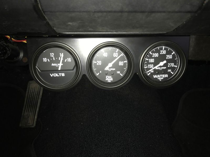
I have a 67 Valiant small block with factory wiring. I have a sqaure back alternator (75 dart) with 2 fields but the car wiring didn't come with 2 field wires and I noticed that the 2nd field was grounded which is overcharging at idle (15.2) so I unplugged it and it reads (12.4). I also have the solid state OE replacement VR. I had the alternator and battery checked and both are good. I replaced the VR with another new one (same style) still same issue. IF I keep this sqaureback where do I run the other field to and can I keep the same style regulator or do I have to upgrade to the newer style VR and will it mount in the same place as the old style? I'm trying to keep it as stock looking as possible.

Picture 4603.jpg


Picture 4604.jpg
 
Did it top out at 15.2 or was it acting like a generator.
If that was max voltage, I would drive it around for about 20 minutes and see if it drops to the 14 zone.
I do the grounded second field all the time, and never have a problem
 
I believe a fully charged battery should be closer to 13.2 volts. All thought a little high at 15.2V, looks like the alternator is putting out to charge the battery. Maybe try charging the battery on a stand alone charger to get it closer to a full charge and then check your measurements again on car.
 
When I first took it off and started it up it slowly crept up to the 15.2 in stages and then stayed there. It isn't actually driveable yet,I have to swap the axle out to swap gears and grease the axle bearings. I'm just trying to get as many bugs worked out as I can so it will be driveable to work out any others that may pop up. I put this alternator in before I restored the car 3 years ago because the previous one and overcharged and blow my link out.
 
I believe a fully charged battery should be closer to 13.2 volts. All thought a little high at 15.2V, looks like the alternator is putting out to charge the battery. Maybe try charging the battery on a stand alone charger to get it closer to a full charge and then check your measurements again on car.

Fully charged batteries should have a static charge in the 12.4 - 12.6 v zone...

Minimum charging voltage is 14.3 and maxumum is 15.0
 
do NOT drive it with it charging that high as that will fry bulbs/electrical devices that are "on" (they ain't made to handle 15+ volts). You have the blue wire to the OE type "box" reg then the green wire from the reg "fld" terminal out to the alt, to one of the alt field terminals and the other alt male field terminal is grounded to the alt case? Most common is a bad reg. the alt innards are OK cuz you had it tested & assuming the green wire ain't grounded. also the battery must be fully charged & able to take/hold a charge (not sulphated or other battery specific ills).
 
We did this two weeks ago to my 67. Squareback 100 amp alternator with an electronic VR conversion. This is how we wired mine.
21.gif

And this was the result at idle
727D6CE5-A9D3-4784-A055-C676F77894F4_zps8qyueywx.jpg
 
Using the meter to measure voltage at the blue (IGN) terminal with engine running is helpful. If the voltage reads about 13.8 to 14.2V, the alternator and regulator are working fine. The high battery voltage happens when there is voltage drop between battery and blue (IGN) circuit, typically occurs at bukhead connectors. Fix drops, battery voltage will be normal.
 
I ran the blue wire like Brian suggested and it actually puts out less (12.1). Do I have to run the newer regulator to match the alternator or can I use the solid state older style? I'll double check the bulk head connections too. I connected the blue wire to the start side of the ballast. Does it matter? I am not much on electronics so it's a learning curve for me.
 
Last edited:
It is not a second field. Both early and late style alternators only have one field. The difference is that on early alternators the second end of the field is grounded internally in the alternator . Later styles with the solid state voltage regulators ground it in the regulator, thus the second field terminal. It doesnt matter which end of it you ground to use it in an older car.

Have you ever had your volt meter calibrated? Have you tried a different battery in the car? As was stated, drive it for a bit, it could just be trying to top up the battery or trying to charge a battery with a bad cell.
 
Brian showed two schematics, the left one is for early regulator. If you wired for one on right, it will not work with early regulator. No need buy newer style regulator unless you want to wire to circuit on right.

Fix the wiring back to what it was when one field terminal grounded. Then with engine running, provided voltage measurements for blue wire at regulator, and battery.
 
I used a multimeter and an aftermarket guage at the battery terminals and both read the same. I had the battery tested and they said it checks out and no dead cells. I ran a jumper terminal from the 2nd FLD to the blue wire on the old style/solid state VR and it is still in the 12's (per a few members). I took the bulk head wiring plugs off and inspected them and they are clean. All I have to do to switch it back is pull the blue wire I ran. I will get some more readings tomorrow
I'll keep you posted.
 
Beware! Using a wire to jumper on a regulator may result in damage to regulator or other problems.

Early style regulators energize the field with (IGN) power with relay contacts or transistor as necessary, the other field connection is ground. In the early alternator, the field brush was grounded to case. The newer alternator needs one terminal grounded, the other goes to field (FLD) terminal on early regulator.

The later style regulator pulls the (FLD) to ground, with transistor to excite the field, the other field terminal is connected to (IGN) for power. The field is just an electro-magnet, it spins, and creates voltage in the stator windings. The intensity of the field is controlled by the regulator looking at the IGN voltage. In both circuits, ground at the regulator case is essential.

The problem of over voltage in your first post, often happens when the alternator output to battery, has voltage drop to (IGN). The regulator works to make (IGN) correct, that is why a voltage reading of (IGN) is important, for trouble shooting.
 
I have a 67 Valiant small block with factory wiring. I have a sqaure back alternator (75 dart) with 2 fields

It sounds like you are keeping the 69/ earlier regulator?

1...Does not matter which field you ground

2...You most likely have a harness or grounding voltage drop. I've made hundreds of posts about this, there are different ways to check

A....Battery "hot" side. You are looking for voltage drop from the battery through the various parts of the harness/ connectors/ ignition switch and back out to the regulator BAT connection. ANY voltage drop here will ADD to the charging voltage.

One way to check this is to rig one terminal of your voltmeter to the regulator BAT terminal (IGN). Rig the other to battery positive, direct to the battery.

Run the engine fast enough to charge and read the meter. The lower the reading the better. More than a few tenths of one volt is too much, and indicates a bad connection in that path, and might be right in the ignition switch itself. You have to chase it down

B.."ground" side. Again with the engine running, and charging, stab one probe of your meter right into the mounting flange of the regulator, and the other probe into the top of the NEG battery post. You should read nearly zero volts, again the lower the better. More than 1 or 2 tenths of one volt, get busy and chase down the ground path

C....If the above tests are OK, try a different battery. "Known good" and "known charged."

D...If the above tests OK, then replace the regulator.
 
Haven't seen you in while, Del. Sounds like you came back at a good time
 
It sounds like you are keeping the 69/ earlier regulator? I was hoping to keep my engine bay stock but with some stock upgrades. I'm assuming that I can't swap one without the other even if the replacement is the solid state/old style? I will do those tests in a little bit. I am not able to drive it in my area because 1) I'm right by an overzelous police dept and they ticket for any and everything, 2) it's not legal yet,3) I need to take my whole rear suspension apart to make it driveable. The modern VR I have is wider than the raised ribs the old VR mounts to. Thanks for the input
 
I did the ground of the VR to the ground on the battery and I get 0.10 - 0.13V. I also did a test from the + on battery to the blue wire/ign on my VR and get 12.20V without the alternator field grounded which is the same I get by testing the battery alone at idle.
 
I did the ground of the VR to the ground on the battery and I get 0.10 - 0.13V. I also did a test from the + on battery to the blue wire/ign on my VR and get 12.20V without the alternator field grounded which is the same I get by testing the battery alone at idle.
you would need to ground the 2nd alt field terminal to get current flowing to get a voltage drop number between batt + post and reg blue wire (ign) terminal you are testing. have it at a fast idle & run it for just a short minute just long enough to take a reading (assuming your overall charging rate is still in the 15's).
 
... I also did a test from the + on battery to the blue wire/ign on my VR and get 12.20V without the alternator field grounded which is the same I get by testing the battery alone at idle.
A gazillion posts about this, but most people need it summarized for them.
By unplugging the field gnd connection, you disabled charging and thus see just battery voltage (should be 12.6 V fully charged).
When charging system works correctly, you should measure IGN to BATT- as 14.3 V. I bet your VR is good and you would measure that, right at the VR.

The VR can only control what is sees. You have minimal drop thru the gnd connection, so that is good. Personally, I don't trust sheet-metal screws so run a dedicated gnd wire to the case. You likely have excessive voltage drop from BATT+ to "IGN at the VR". That path is thru the bulkhead, key switch, bulkhead again, then VR. The bulkhead is ususally the problem. Search "MAD Bypass". That disables the dash ammeter, but you can use a cigarette-lighter voltmeter to monitor charging while driving. Smart on long trips so no surprises. Harbor Freight sells a cheap LED-light version, but lay out $15 for a better digital one (Amazon, ...).
 
One other thing to consider it the later alternators put out much higher amperage then the original and the ammeter can't handle that for long before it fails and leaves you stranded .

Run a 10 gauge wire from the alternator to the starter or battery to carry the load.
By pass the ammeter by moving one lead to the other post so both wires are on the same post. Install a volt meter.

Of course check for voltage drop from the battery + to the + terminal of the voltage regulator. This will test the bulkhead , ignition switch and ammeter bypass connections.
 
BTW, I should repeat that those w/ a 1963 or 1965 car (any body, but not 1964), can keep their ammeter operational. The reason is that those bulkheads use thick "buss bars" to feed the large ALT and BAT wires thru. Of course, other-year cars can to the same by running dedicated thick wires thru, instead of the "57 terminals" which were used. The factory did that for some taxi/police orders (termed "fleet bypass"). Apparently, they decided the cheaper spade terminals would last thru the warranty for commoners, and most original owners back then bought a new car every 3 years (watch Mad Men), and the company didn't care what problems 2nd-hand purchasers (i.e. bottom-feeders) experienced. Seems the engineers realized the "melted bulkhead" problem in 1964, hence fixed for 1965, but probably an accountant nix'ed that for 1966+.

If you do keep your dash ammeter active, insure the ring terminal connections are solid, since corrosion or loose-ness (then melt-down) has been seen. If you upgrade to a higher output alternator, you would over-range the ammeter (i.e. smoke). I designed a diode-shunt bypass for my cars which progressively bypasses in the engine bay (see post), but most here couldn't follow that so just install a permanent shunt wire.
 
-
Back
Top