You are using an out of date browser. It may not display this or other websites correctly.
You should upgrade or use an alternative browser.
You should upgrade or use an alternative browser.
Sub-frame connectors... Please build them correctly!
- Thread starter 4mulaSvaliant
- Start date
-
67Dart273
Well-Known Member
Who made these?
They appear to the the US Cartool pieces.
That would be my "only a guess." Those seem to get a good reputation
longarm
Car sold back to original owners
To say these cars were poorly built does not take
into account how they are designed to fold up to
dissipate energy.
To add all the strength of these mods defeats the
manufactures design.
Having said this, I don't care and welded in US Car Tool ties
and will be adding torque boxes.
I believe welded in adds more strength but anything is better than nothing.
What you consider sub-standard works extremely well on my car ,it takes the twist out helping the launch. I certainly would not like the extra humps in the floor on a non- race only car . If its race only the cage will negate your extra work .I guess I have always done it wrong, every one I have done was met with a wow what a difference thanks man .
turbofreek
batcrap crazy racing team
you all did it wrong. ill take mine over any pictured in this thread.
67Dart273
Well-Known Member
you all did it wrong. ill take mine over any pictured in this thread.
Incredible answer. You must work for Microsoft. Even though your answer was technically correct, it really wasn't very helpful
Blame Sedanman. All his fault for stirring this up again. ;)
Like I said before, until someone does a full stress/strain analysis on a complete chassis and compares the different types of subframe connectors it's all just guessing. Until that happens, saying someone is "doing it wrong" makes assumptions that can't be scientifically justified. All of the "evidence" that anyone has is pretty much anecdotal. The chassis and body structure are too complex to just "wing it".
Heck, even if someone did do a full on computer model with a stress/strain analysis there would still be points to argue, based on the assumptions that have to be made in order to model welded joints in both the original structure and the subframe connectors. It would be much easier to model the tubular subframe connectors, the contoured and welded to the floor type would be a royal PITA to model for analysis. And they way that they get modeled absolutely has an effect on the end results. Or maybe we should compare two cars with different style connectors using dynamic loads in the real world? Consider the lousy quality control when they left the factory, then consider it's 40+ years later. How much hidden damage is there? Who knows. Maybe one of the cars has a couple extra spot welds because it wasn't Friday afternoon. Test 50 cars and maybe you're getting somewhere, but who's going to do that?
All of the different types of subframe connectors out there are better than nothing. Better than each other? Good luck. The Hotchkis Taxi is a full second faster than a 2012 3 series BMW on TireRack's test track with TireRack's driver. Meaning, in a one day test with a 1970 4-door Satellite he beat his own best time in a 2012 3-series BMW that he makes hundreds of laps in. And since I have a set of Hotchkis subframe connectors that I'm currently installing on my Challenger, I can tell you they aren't even the strongest subframe connectors I've seen. The ones I built for my Duster myself at home are stronger, at least comparing subframe connector to subframe connector. But obviously the Hotchkis pieces work, even if they're not the beefiest, or biggest tubes and even if they don't get welded to the floor.
longarm
Car sold back to original owners
you all did it wrong. ill take mine over any pictured in this thread.
I'll bites, so what is superior about yours as opposed to all others.
turbofreek
batcrap crazy racing team
I'll bites, so what is superior about yours as opposed to all others.
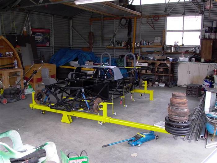
glad you asked...any questions?
Attachments
turbofreek
batcrap crazy racing team
72Valiant4Door
Trouble Maker
I don't even understand the debate, other than a response to the borderline rude nature of the commentary.
Tying in the sub-frames to the floor is going to be substantially stronger, than just touching a frame to the other frame.
Whether the lesser works great, doesn't matter. In the case of rigidity and strength, this more is better.
In the end, though, what are you trying to achieve? Sometimes you want flexing to achieve your goal, sometimes you absolutely do not. Sometimes you want less weight, sometimes it doesn't matter.
Don't get a titty twisted over it.
last one. notice the support from the rocker to the connector? thats the thickest part of the cente rof the cwr as mentioned earlier in this thread.
Your subframe connectors look pretty beefy, I bet they're plenty strong.
The floor, on the other hand, is not. If it's a full cage car it doesn't matter much, but if the subframe connectors are the only reinforcements you'll need more, as the floor pan lacks the strength of the originals. There's a reason the floor pans weren't just flat sheet metal, and it's not because Ma Mopar cared about the ergonomics of having footwells. All of those stampings, varying heights and contours add rigidity and torsional resistance.
I don't even understand the debate, other than a response to the borderline rude nature of the commentary.
Tying in the sub-frames to the floor is going to be substantially stronger, than just touching a frame to the other frame.
Whether the lesser works great, doesn't matter. In the case of rigidity and strength, this more is better.
In the end, though, what are you trying to achieve? Sometimes you want flexing to achieve your goal, sometimes you absolutely do not. Sometimes you want less weight, sometimes it doesn't matter.
Don't get a titty twisted over it.
One extreme to the next, straight from the floor pan is irrelevant to it's the source of unsurmountable strength.
You're ignoring the rest of the chassis as a system. How much stronger can you make the system without a cage? You have no idea if the actual torsional loads on the car are better resisted by a set of thinner, floor welded subframe connectors or a set of thick wall, fully boxed connectors that are not tied to the floor. If the subframe connectors are sufficiently rigid, and are tied appropriately into the subframes, the movement of the subframes is significantly limited, and therefore the floor pan is more isolated from the torsional loads. It's not a like to like comparison, the contoured floor welded connectors are often half as thick as some of the tubular subframe connectors, and the contoured connectors have some sections where they have a very small cross sectional area than wider tubular connectors. But it's not just about the connectors, its the entire chassis.
Bottom line is, you have no idea which one works better. Both have been proven anecdotally to work on the street and on the track, both in a straight line and in the corners. Which one is actually better would require modeling analysis or a series of dynamic testing with a large number of cars, neither of which will ever happen.
turbofreek
batcrap crazy racing team
I don't even understand the debate, other than a response to the borderline rude nature of the commentary.
Tying in the sub-frames to the floor is going to be substantially stronger, than just touching a frame to the other frame.
Whether the lesser works great, doesn't matter. In the case of rigidity and strength, this more is better.
In the end, though, what are you trying to achieve? Sometimes you want flexing to achieve your goal, sometimes you absolutely do not. Sometimes you want less weight, sometimes it doesn't matter.
Don't get a titty twisted over it.
sarcasm is a tough thing to express in text.
but the simple fact my subframe connectors are not just a strait shot. they go all the aay up the frame rail into the front and rear factory frame. then they also connect on both ends of the rocker panels crating a torsional stiffening of the car. yes i also have a massive cage as well but the foundation of the cage is off those same rails to the rockers. without the floor even in place it was on a lift and didnt flex a millimeter.
GeorgeH
Well-Known Member
glad you asked...any questions?
similar fashion to how I did mine
http://www.forabodiesonly.com/mopar/attachment.php?attachmentid=1714778035&stc=1&d=1419234056
http://www.forabodiesonly.com/mopar/attachment.php?attachmentid=1714778034&stc=1&d=1419234056
peeled the frame rail caps off and stubbed them into rails as far as they could go.
turbofreek
batcrap crazy racing team
yep pretty close. mine is welded all the way down the rail and then the top plate was welded back on with thicker material. welded on all sides the length of the insert into the rail. not really a better way to do it. i like the extended use of the existing frame rail a lot. those diag bars to the rocker are key. there is very thick metal there for structure support. i feel it is key to torsional displacement of the connector. if a cage is not being used that would be how id do it anyhow.
71DodgeDemon340
Well-Known Member
you all did it wrong. ill take mine over any pictured in this thread.
Oops im sorry my properly fitted fully welded sub frame connectors for my street car are wrong
 ops:
ops:Before everyone says this is wrong. mine is right blah blah you should take in consideration for the type of project being done, these weld in connectors are absolutely 100% practical for most of us who have street cars, I noticed a big improvement of launch and handling. To say that these are incorrect is ridiculous. However the prep and weld procedure is crucial. what works for some may not work for others and what works for others may not work for everyone, all boils down to build. And welding the front and rear of the connectors to the subframes and floor is completing a box thus in turn making it a full frame. If I remember correctly i believe the connectors i got were 3/16" thick, plenty strong
bentdart47
FABOlous
Take this for what it's worth. My Dart had bolt on style subframe connectors. They went front to rear and also bolted up through the front seat area. When I would jack up the car I could hear the them shifting slightly. I figured if they were shifting how well could they be working? I just as of two weeks ago went with weld in style sub frame connectors that followed the contour of my floor pan along with torque boxes front and rear. It's made a noticeable difference in the overall stiffness of my chassis.
451Cuda
Well-Known Member
Blame Sedanman. All his fault for stirring this up again. ;)
Like I said before, until someone does a full stress/strain analysis on a complete chassis and compares the different types of subframe connectors it's all just guessing. Until that happens, saying someone is "doing it wrong" makes assumptions that can't be scientifically justified. All of the "evidence" that anyone has is pretty much anecdotal. The chassis and body structure are too complex to just "wing it".
Heck, even if someone did do a full on computer model with a stress/strain analysis there would still be points to argue, based on the assumptions that have to be made in order to model welded joints in both the original structure and the subframe connectors. It would be much easier to model the tubular subframe connectors, the contoured and welded to the floor type would be a royal PITA to model for analysis. And they way that they get modeled absolutely has an effect on the end results. Or maybe we should compare two cars with different style connectors using dynamic loads in the real world? Consider the lousy quality control when they left the factory, then consider it's 40+ years later. How much hidden damage is there? Who knows. Maybe one of the cars has a couple extra spot welds because it wasn't Friday afternoon. Test 50 cars and maybe you're getting somewhere, but who's going to do that?
All of the different types of subframe connectors out there are better than nothing. Better than each other? Good luck. The Hotchkis Taxi is a full second faster than a 2012 3 series BMW on TireRack's test track with TireRack's driver. Meaning, in a one day test with a 1970 4-door Satellite he beat his own best time in a 2012 3-series BMW that he makes hundreds of laps in. And since I have a set of Hotchkis subframe connectors that I'm currently installing on my Challenger, I can tell you they aren't even the strongest subframe connectors I've seen. The ones I built for my Duster myself at home are stronger, at least comparing subframe connector to subframe connector. But obviously the Hotchkis pieces work, even if they're not the beefiest, or biggest tubes and even if they don't get welded to the floor.
No need for computer models, a torsional test will separate fact from fiction. This type of fixture with attachment points at the wheels is the proper method:
No need for computer models, a torsional test will separate fact from fiction. This type of fixture with attachment points at the wheels is the proper method:
That is one way to test for torsional rigidity, yes. Proper? Again, this is totally misleading. The test shows a weighted lever arm applied to the front suspension, but the rear suspension is constrained and even the front suspension is locked out using fixed rods instead of the usual springs and shocks. Yes, it gives you a torsional rigidity number, and it is a fairly common way to test torsional rigidity because it's pretty simple (ie, easily repeatable). But how that number relates to how the chassis actually behaves going down the road is a different story.
In about two seconds I found this nice post on a Formula SAE board. If you don't know, formula SAE (society of automotive engineers) is a yearly competition for college engineering students where they design and race what amounts to a 2/3 scale formula-1 style car powered by a 600cc motorcycle powerplant. I was a member of a FSAE team the first couple years I was in college. Anyway, it's a nice, simple explanation of the shortcomings of the test you show.
https://www.reddit.com/r/FSAE/comments/39rpow/best_way_to_test_simulation_and_physical_chassis/
My point here isn't to be contrary. My point is that there are dozens of different methods to test something like how subframe connectors will effect the chassis, all with varying degrees of accuracy and relevance to the real world. And even among engineers, you will run into a spectrum of opinions on which tests are most valid. The test you show is just a single method, and in a lot of cases it's just used to compare the results of a computational model to a simple real world test to check the validity of the computer model that was used. If the model lines up with the results of the test then the computational model can be used to determine more relevant loading scenarios.
And even if you accepted that particular test as the standard benchmark way to conduct your tests (which is reasonable, and that test is used as a benchmark for certain applications), all you could really say at the end of it was that in that particular test one type of connector outperformed the other. It's not an end-all, be-all kind of deal, as the short discussion I linked helps to point out.
451Cuda
Well-Known Member
That is one way to test for torsional rigidity, yes. Proper? Again, this is totally misleading. The test shows a weighted lever arm applied to the front suspension, but the rear suspension is constrained and even the front suspension is locked out using fixed rods instead of the usual springs and shocks. Yes, it gives you a torsional rigidity number, and it is a fairly common way to test torsional rigidity because it's pretty simple (ie, easily repeatable). But how that number relates to how the chassis actually behaves going down the road is a different story.
In about two seconds I found this nice post on a Formula SAE board. If you don't know, formula SAE (society of automotive engineers) is a yearly competition for college engineering students where they design and race what amounts to a 2/3 scale formula-1 style car powered by a 600cc motorcycle powerplant. I was a member of a FSAE team the first couple years I was in college. Anyway, it's a nice, simple explanation of the shortcomings of the test you show.
https://www.reddit.com/r/FSAE/comments/39rpow/best_way_to_test_simulation_and_physical_chassis/
My point here isn't to be contrary. My point is that there are dozens of different methods to test something like how subframe connectors will effect the chassis, all with varying degrees of accuracy and relevance to the real world. And even among engineers, you will run into a spectrum of opinions on which tests are most valid. The test you show is just a single method, and in a lot of cases it's just used to compare the results of a computational model to a simple real world test to check the validity of the computer model that was used. If the model lines up with the results of the test then the computational model can be used to determine more relevant loading scenarios.
And even if you accepted that particular test as the standard benchmark way to conduct your tests (which is reasonable, and that test is used as a benchmark for certain applications), all you could really say at the end of it was that in that particular test one type of connector outperformed the other. It's not an end-all, be-all kind of deal, as the short discussion I linked helps to point out.
I would agree that's most likely a superior method described in that paper, thanks for the link. It also looks like it might be an easier method for the serious amateur to use in the home shop.
But whichever method is used, my point was to show that there's a way to move the discussion past the blind speculation on a forum and into the real world with measurable results. I've always been curious how important the welding of the floor pan was to the effectiveness of the frame connector, maybe sometime this year I'll test it out. I do have an A-body parts car that's sitting around...
golden boy
Well-Known Member
i have used one by two rec tube .100 wall and ran it under the front and rear existing stub frames overlapping as far as reasonable before the turn up for the wheels. this is super easy to do, doesn't cause any clearance problems, traps torsion cross member in the assembly,(good thing), and creates a box with the floor structure. Doubtful that a 40 year old floor has any structure to contribute. would have tied floor into it if i had the car apart and was installing new floors. i feel that by overlapping onto the stub frames by nearly a foot or more contributes to the rigidity and allows for a large welding area . I tacked mine in place after fitting and had a freind do the welds. (about an hour)
Woods74
Broke Senior
Why this was resurrected, just to recycle the questions and answers is beyond... As far as the whole 'do I weld it to the floor pans?' how do you even entertain the idea? ...
Have you ever glued paper towel wings to a cardboard tube and expected it to fly?

/thread
Have you ever glued paper towel wings to a cardboard tube and expected it to fly?
/thread
So, I can help but notice all of the sub-frame connectors that many people build, and do next to nothing for the rigidity of the car.
I have noticed the common thing to do is to weld some form of tube from the front sub-frame to the rear sub-frame with no attachment to the floor pan itself. This method is next to pointless. Im sure Ill fire up some huge differences in opinion here, but it truly comes down to fact and not ones opinion.
Adding tubing from front to rear will keep your car from stretching.... That's about it... As far I I have ever known, its just not an issue! LOL
So to explain this a little better, there are some basics in building strength into anything, whether it be full tube chassis fabrication or shoring up your twisting little a-body.
By welding in the tube and only attaching it at the ends, you have accomplished exactly the same strength as the rocker panels already produce. They are already there, so why add additional weight?
The correct way to do this is with the laser cut sheet metal sub frame connectors that conform to the floor pans and are meant to be fully welded.
With the new material being welded to the floor pan, you have now tied, the floor to a rail, which in turn is tied to the front and read sub frames.
The correct way to build these to the point they actually provide structured support is shown in the pictures below.
Even the pictures which dont have 100% weld along the connector is better than the "floating" connectors.
Though it transfers much of the torque to the area that is not welded. This creates a high stress area in a pretty concentrated area.
The bottom pictures are the type that do next to nothing for the problematic area in these cars which is the nearly flat plane of the floor pans between the sub frame sections from front to rear.
Im sure this will chap a few hides, but I hate to see this mod over and over and done for nearly no gain.
Well I don't care what those other jokers say. You are right, and I wouldn't say your bashing on anyone.
But you seem to be the only one who thinks it's informative. Just cause it's your way doesn't make it the best way.
Ya know, some people like you need to chill the **** out. And also take your own advice. Just because you didn't weld them fully doesn't make your way as good as fully welding. Yes adding the connectors added strength, but fully welding them would create more strength. But if your gonna go through the effort of putting them on the car you might as well do the whole thing.
I would agree that's most likely a superior method described in that paper, thanks for the link. It also looks like it might be an easier method for the serious amateur to use in the home shop.
But whichever method is used, my point was to show that there's a way to move the discussion past the blind speculation on a forum and into the real world with measurable results. I've always been curious how important the welding of the floor pan was to the effectiveness of the frame connector, maybe sometime this year I'll test it out. I do have an A-body parts car that's sitting around...
I'd love to see someone actually test it. I'm not saying the results wouldn't be helpful, I'm just cautioning that with only a single test, even a good one, that it would still be premature to call one method the "best" way to do it. But I'd love to see someone do some testing and provide results that aren't completely anecdotal.
Why this was resurrected, just to recycle the questions and answers is beyond... As far as the whole 'do I weld it to the floor pans?' how do you even entertain the idea? ...
Have you ever glued paper towel wings to a cardboard tube and expected it to fly?
/thread
You can weld the connectors to the floor pans. It's not a trivial exercise from a welding skills point of view though, and unless you have the car on a rotisserie after some kind of blasting or metal stripping it's a royal PITA. But it absolutely can be done, and given how important the floor pan is for the structural integrity of these cars it definitely makes sense from a chassis stiffness and torsional rigidity standpoint. Lots of folks have done it successfully, and there's not doubt that it improves the stiffness of the chassis.
Whether of not it's the "best" method I certainly can't say. If you want your connectors to look somewhat factory, and are tearing the car completely down to the chassis and putting it on a rotisserie I don't think they're a bad way to go at all.
-


