Turbocharger for 318 project

-
cool project! I think one day I would love to do a turbo engine! i know absolutely nothing, but about the chinese turbo u listed mad dart, how do they compare to the USA made units? what is a common USA made turbo? i am just wondering, for i do not know.

To answer the USA question.... I don't know of any off the top of my head that are completely built in the USA.
 
Yah mad dart I grabbed these pics from a member on the Turboforums.com I plan to turbo my 1999 ram 2500 this summer and ill either do it with the truck manifolds or a set of shorties flipped around.
 
Ok Louis, thank you for taking the time to answer. :) I know which turbo to choose one day!!!
 
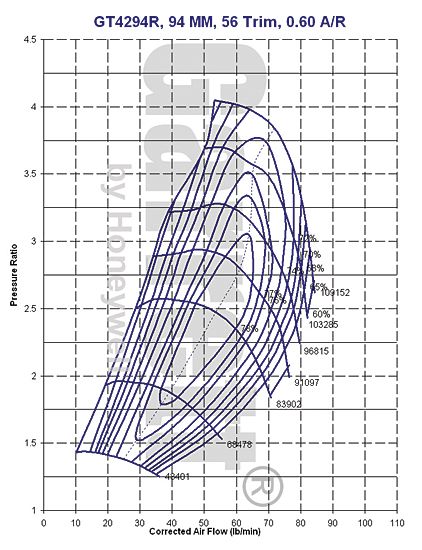
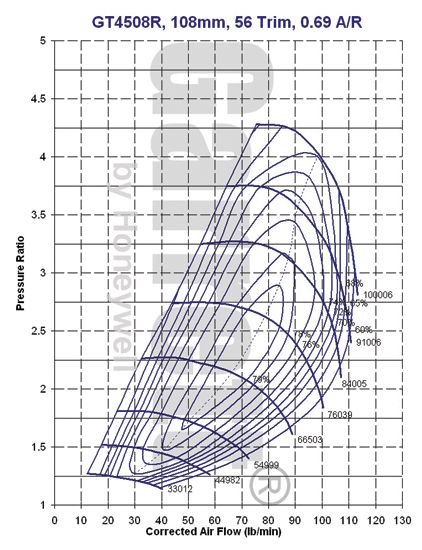
The second map is better, more efficient in the 79% efficiency range. With room to increase the pressure and airflow and still be in the sweet spot of that map. The first map you only have a small window to increase the pressure/ airflow and then you will be out of the sweet spot of that turbos capabilities.
 
Prine or any one else, Please
I have found this turbo sizing chart all over the internet. BUT I'M TO DUMB(math wise) to figure it out!

This is what confuses me every time.
T2 = T1 (P2 ÷ P1)0.283

Could you spell this out for me...........The 0.283? what do i do with that?
Most, have some math symbol between the" ) and the 0.283"
Thanks

I also want to do something that will hopefully help everyone who is interested in maybe doing a future turbo project.

I will SHOW everyone,....THE FORUMLA's for sizing turbochargers.

When using the formula's below, you will need to use compressor flow maps and work with the formulas until you size the compressor that will work for your application. Compressor flow maps are available from the manufacturer, do a search on the web, I suggest http://www.turbobygarrett.com/turbobygarrett/ they have flow maps for every turbo they sell. On the flow maps, the airflow requirements should fall somewhere between the surge line and the 60% efficiency line, the goal should be to get in the peak efficiency range at the point of your power peak. In this article I will walk through an example as I explain it.

In order to select a turbocharger, you must know how much air it must flow to reach your goal. You first need to figure the cubic feet per minute of air flowing through the engine at maximum rpm. The the formula to do this for a 4 stroke engine is:
(CID × RPM) ÷3456 = CFM
318 x 6500 / 3456 = 598.02
The engine will flow 598 CFM of air assuming a 100% volumetric efficiency. Most street engines will have an 80-90% VE, so the CFM will need to be adjusted. Lets assume our 318 has an 85% VE.

318 x 0.85% = 508

So the engine will flow 508 cfm at 85% VE

PRESSURE RATIO
The pressure ratio is simply the pressure in, compared to the pressure out of the turbocharger. The pressure in is usually atmospheric pressure, but may be slightly lower if the intake system before the turbo is restrictive, the inlet pressure could be higher than atmospheric if there is more than 1 turbocharger in series. In that case the inlet pressure will be the outlet pressure of the turbo before it. If we want 10 psi of boost with atmospheric pressure as the inlet pressure, the formula would look like this:
(10 + 14.7) ÷ 14.7 = 1.68:1 pressure ratio.


A compressor will raise the temperature of air as it compresses it. As temperature increases, the volume of air also increases. There is an ideal temperature rise which is a temperature rise equivalent to the amount of work that it takes to compress the air. The formula to figure the ideal outlet temperature is:
T2 = T1 (P2 ÷ P1)0.283
Where:
T2 = Outlet Temperature °R
T1 = Inlet Temperature °R
°R = °F + 460
P1 = Inlet Pressure Absolute
P2 = Outlet Pressure Absolute
Lets assume that the inlet temperature is 75° F and we're going to want 10 psi of boost pressure. To figure T1 in °R, you will do this:
T1 = 75 + 460 = 535°R
The P1 inlet pressure will be atmospheric in our case and the P2 outlet pressure will be 10 psi above atmospheric. Atmospheric pressure is 14.7 psi, so the inlet pressure will be 14.7 psi, to figure the outlet pressure add the boost pressure to the inlet pressure.
P2 = 14.7 + 10 = 24.7 psi
For our example, we now have everything we need to figure out the ideal outlet temperature. We must plug this info into out formula to figure out T2:
T1 = 75
P1 = 14.7
P2 = 24.7
The formula will now look like this:
T2 = 535 (24.7 ÷ 14.7)0.283 = 620 °R
You then need to subtract 460 to get °F, so simply do this:
620 - 460 = 160 °F Ideal Outlet Temperature
This is a temperature rise of 85 °F


Then You need to Know the Density Ratio;
As air is heated it expands and becomes less dense. This makes an increase in volume and flow. To compare the inlet to outlet air flow, you must know the density ratio. To figure out this ratio, use this formula:
(Inlet °R ÷ Outlet °R) × (Outlet Pressure ÷ Inlet Pressure) = Density Ratio
We have everything we need to figure this out. For our 318 example the formula will look like this:
(508 ÷ 656) × (24.7 ÷ 14.7) = 1.36 Density Ratio

Now you can figure Compressor Actual Inlet Flow
Using all the above information, you can figure out what the actual inlet flow in in CFM. Do do this, use this formula:
Outlet CFM × Density Ratio = Actual Inlet CFM
Using the same 318 in our examples, it would look like this:
508 CFM × 1.36 = 690 CFM Inlet Air Flow
That is about a 37% increase in airflow and the potential for 37% more power. When comparing to a compressor flow map that is in Pounds per Minute (lbs/min), multiply CFM by 0.069 to convert CFM to lbs/min.
690 CFM × 0.069 = 47.6 lbs/min
Now you can use these formula's along with flow maps to select a compressor to match your engine. You should play with a few adiabatic efficiency numbers and pressure ratios to get good results. For twin turbo's, remember that each turbo will only flow 1/2 the total airflow.

USING YOUR NUMBERS
A turbocharger compressor map has two axis. On the x-axis (the horizontal one) is the airflow, often in lbs/minute. On the y-axis is the pressure ratio, usually as "1+boost pressure", in bar. Inside the map there are plots for turbine rpm, more or less horizontal lines, efficiency (oval rings) and most often also surge limit - a dotted line.
To use the map, you need to know the airflow you will have through the engine.
Using this value, you can use a map. Draw a line from your air flow (lbs/min) on the x-axis, and a line from the pressure ratio (psi + 14.7 ÷14.7 ). The point of intersection will hopefully be inside one of the higher efficiency rings, about 70%.
You should always have the intersection to the right of the surge limit, otherwise it is no good.
The way to do this is to plot 5-10 intersections (different rpms and boost pressures) in different maps. By having maps for different turbos, and trying different boost pressures and rpm, you can get an idea of how it’s going to work.
Remember this only gives an estimate, you might have to resort to trial and error to get exactly spot on. This way, however, you can be reasonably sure you are in the right ballpark


1 Bar = 14.6 PSI
1 PSI = .06 Bar


When Looking at this Flow Map for a Garrett GT4294R, you can see where all your numbers from the formulas' come into play....
GarrettGT4294RFlowMap_zps2384c58b.jpg


You can see that At : 1.36 Density Ratio....the turbo is spinning.....and at this ratio it is plotted on the map.....it is flowing 35 to 42 lbs per minute.....barely humming along.

There is much more CFM flow to be gained by increasing the PRESSURE RATIO
But You can also see that this particular turbo is almost too small for a 318.....unless 650-700hp is all you want.

It will flow 450-700hp, but at that flow, and Pressure Ratio....it is heating the air, and on the edge of the ÜSEABLE map.

Now Lets look at a Different Map

GT4508R_Comp_zps5e3c498f.jpg


You can see how the airflow moved up and to the right......

Which one is better?

:happy1:


Mad Dart Wrote:The second map is better, more efficient in the 79% efficiency range. With room to increase the pressure and airflow and still be in the sweet spot of that map.
In my case, using the 318 of the OP, the first one is a better choice. Why? because of the different pressure ratio created by higher altitude, that i live at.
Even thought the turbo is often called a altitude compensater it still will affect your choice on a turbo.

If you input 11.8 (average air pressure were i live) in place of the standard 14.696. you will see that it changes the maps. Causes the GT4508R to be running close to the 72% line and never make it into the sweet spot. Were as the GT4292R comes up the 78% line and then runs straight across the sweet spot or best afficany(sp) line.

THANKS for the link MD, been having a lot of fun mixing it all up :coffee2:
http://www.squirrelpf.com/turbocalc/

With all of these calculators/maps etc , they are only for reference to have a ball park of where you will end up. For example on my set up I have a 410 CU Small Block Stroker. I know from experience that it should make right at 500HP Naturally Aspirated before the Boost is entered into the equation. Solid Roller cam etc............

On Squirrels calculator when I input my specific engine characteristics it is saying I will need 16PSI to get to 800hp for example. I know plenty of combinations pretty close to the same as mine running the same Turbo's that I have that are hitting close to 900Hp to the tires on only 11PSI. It comes down to how efficient your engine is as to how it will actually react in a "Real World" Scenario. Intake Charge Temp "Inter-cooled/Meth Injection", "Head Flow" Compression and camshaft choice will all come into play.
 
I here you, boost ##s are not the final answer. Was just making a point that altitude can change up the ##s as well.
 
I know this is a dead post, and i dont mean to hijack but would a cummins holset hx35 work for 318 street car? I dont want 5-600 hundred horse. Just some added fun. I was thinking about a 318 with 360 heads and a turbo. Is the hx35 to small for a single? I figured itd do okay on a little 318 means it pushes a cummins 5.9
 
What size wastegate would work best with the turbo? The two main reasons i liked the holset is how cheaply i can pick one up (seems like everyone around here has a cummins they have swapped or are swapping) and the fact theyre ingernally gated which seems easier to run on a custom fab.
 
Apples to oranges. That turbo is too small for a single setup, but would be perfect for twins though. If you want a cheap single then this is what you need. Perfect for up to ~600 hp and your 318 will spool it no problem.

http://www.ebay.com/itm/GT45-HUGE-V...Parts_Accessories&hash=item230f5de211&vxp=mtr

Hi, just a thought............on these threads, ebay links "go away" in a fairly short time, would be helpful if you guys'd post pertenent info about the auction, AKA...............

[SIZE=+0]GT45 HUGE V-BAND 1000+HPS TURBO/TURBOCHARGER CAMARO GT

[/SIZE] TBC-GT45
TheGT-45 Turbocharger is a larger turbo capable of generating 1000+ hp, depending on application and with the correct tuning. The GT-45 can handle a peak boost of 25-35 psi. The GT-45 is generally used for larger displacement engines of 3.0L and up, since these types of engines can produce enough exhaust volume to push the GT-45.
Compressor Size: Inlet = 4 3/16", Inducer = 68.7MM, Exducer = 97.8 MM, Trim = 69,A/R = 0.66, Intake (ID / OD) = 2.25" / 3.25"
Turbine: Outlet = 4", Turbo flange = T4, Downpipe flange = 3.5" V-band, Inducer = 87.4 MM, Exducer = 77 MM,Trim = 92, A/R = 1.05
APPLICATION: UNIVERSAL FOR TURBO MANIFOLD WITH T4 FLANGE


Seller information

dnamotoring (44541
 

and................

Seller information

drifteffects
RS-SERIES 60mm V BAND TURBO WASTEGATE 5.5" TALL 12-14-19-31 PSI garrett kkk borg

GODSPEED RS-SERIES 60MM WASTEGATE V-BAND


DESCRIPTION: GODSPEED 60MM V BAND RS-SERIES WASTEGATE (universal)


- comes with 5psi spring x 1 , 14 psi springs x 1 , 12 psi springs (combine up to 31 psi)
- dual port. accurate boost
- ultra durable diagram (diaphram)
- comes with all the hardware (bolts, gasket etc)
- accurate boost pressure
- high quality appearance
- simple one step process for removing or installing different wastegate springs
- 1 year warranty ( if installed by professional)

this wastegate is 5.5" inches tall.

5 psi spring : outer diameter : 36.5mm / length : 75mm
12 psi spring : outer diameter : 59mm / length : 121mm
14 psi spring : outer diameter : 49mm / length : 108 mm

example : you can use 5 psi spring by itself or the 12 psi or 14 psi spring by itself. Using 5 psi + 14 psi with result in 19 psi . Using all three springs together will get you up to 31 psi max.

doesn't come with installation instructions
ALL ITEMS ARE BRAND NEW
PLEASE CHECK OUT MY OTHER AUCTIONS
FEEL FREE TO CONTACT US
PHONE NUMBER : 1-626-926-6465 MON-FRI 10AM-6PM PST
 
-
Back
Top