could i possible have got the wrong alternator that my voltage regulator cannot regulate..
No, there is pretty much no such thing. I've used Chrysler regulators on Delcos, Fords, and right now, have the early (69 / earlier) style regulator on a Toyota alternator on a tractor
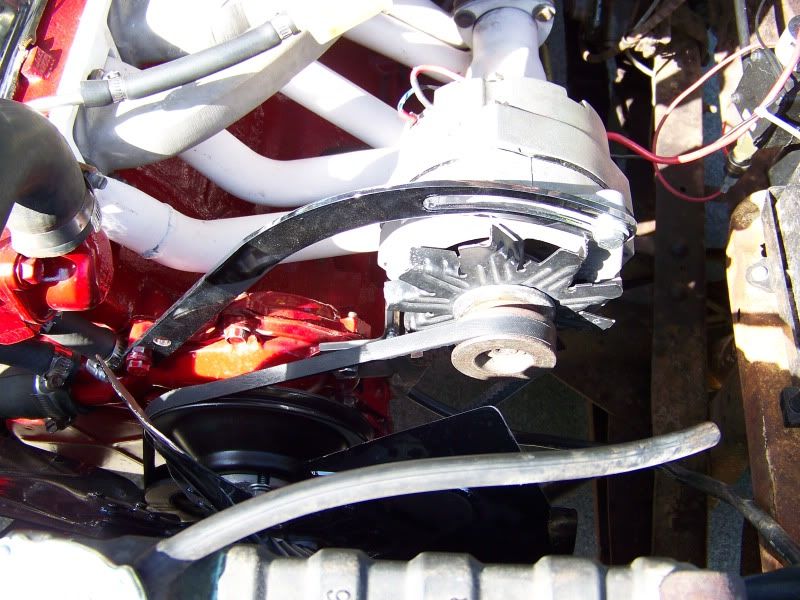
the alternator came with one field tab, a vacant field tab, a ground tab and the battery post. because my previous alternator had two fields i removed one of those tabs and put it on the new alternator. i currently have both fields hooked up and the battery post, not using the ground.
It's difficult to picture what you've done here, it's POSSIBLE that the regulator is not even in the circuit, that is, you have created a situation where the alternator is being "full fielded" and charging full output regardless
are there different spec,d voltage regulators? could i possibly have a racing version that allows a higher out put? .
the short answer is "no." They call them voltage regulators for a reason--they regulate voltage. All vehicle lead acid batteries are pretty much the same, and therefore require the same voltage---the target is about 13.8V, depending on which book you read
On the assumption that it's wired wrong or maybe has a wireing problem (short in the harness)
First pull off one "push on" connector AT A TIME from the alternator and confirm that it stops charging. Then pull the connector off the regulator and confirm that it stops charging.
If not there's something you must understand-----rebuilders do things. Some rebuilders take the old style "grounded field" cases and modify them to install an insulated brush in order to sell them as the newer (70/ later) "isolated field" unit. The PROBLEM with this is that some of these brush holders are CS and subject to failures I.E. grounding. What this means is, that you really have a 69/ earlier grounded field unit and the regulator won't work, and if you happen to hook the ign supply to the wrong terminal, it shorts to ground.
So to check out the above situation, pull loose BOTH field connections at the alternator AND pull the regulator connector. Now with the key on (run position), use a test lamp/ meter and see which field WIRE shows hot at the alternator. THIS IS YOUR hot feed coming from the key.
Hook ONLY this wire back onto the field, and with the key in "run" check the UNCONNECTED field terminal on the alternator. IT SHOULD show 12V or give you a "test light."
If this shows OK, make no changes to the above and start the car. IT SHOULD NOT CHARGE. If it does not, the wiring is OK so far.
Now hook up the second field wire, but LEAVE the regulator connector OFF. IT SHOULD NOT CHARGE. Shut off the engine.
IF above checks as described, temporarily probe the regulator harness connector terminals with key in "run." You should get a light or show 12V on BOTH connectors. Now temporarily DISCONNECT one field wire at the alternator. AGAIN probe the harness connector at the regulator, and now only ONE terminal should be "hot" the other dead. The hot terminal should be the one at the "top of the triangle"
OK let's say the above checks show OK NEXT thing to do is find out what else is up, so do my "always do this" tests.
The regulator MUST be operating under two conditions to "be correct" assuming the regulator is not defective----
first, the "ground" or case of the regulator MUST be at the same voltage as the battery neg. post.
second, the ign supply terminal MUST be very near to battery positive voltage, this is the so called "sense" lead as well as the supply power to the regulator / field.
To determine this, first run these tests with all accessories off, then repeat with headlights, heater on. With engine running at a good fast "low cruise" RPM,
stick one probe of your multimeter directly on the battery negative post. Stick the other probe directly onto the case of the regulator. You should read VERY low voltage, the lower the better, zero is perfect. More than about .2v (two tenths) is too much, and shows that you have a ground problem between the battery/ engine/ body/ regulator
Next, check the "hot" side. Stick one probe of your meter directly onto the battery positive post. Stick the other probe directly onto the ignition supply to the regulator. Probably the closest point is the "high" side post of the ballast. SAME AS above, you want zero is perfect, no more than .2V. Higher voltage indicates a VOLTAGE DROP in the harness somewhere. This can be a bad splice, bad connection(s) at the bulkhead connector, bad connector at the ignition switch, or even the switch itself, or the supply lead feeding the switch on the "hot" side of the switch---and back out through the bulkhead AGAIN.
ALTERNATELY you can check this by substitution. Temporarily connect a good big jumper, say, no 10 or even bigger, from one of the mounting bolts on the regulator to the battery negative terminal.
For the supply, temporarily connect a nice big no10 wire from battery positive to the "ign" terminal of the ballast---should be original blue, I think, feeds the ballast, the regulator "ign" and the second field terminal of the alternator.
Of course make sure the battery cables are in good shape, clean and tight.
THE ONLY DIFFERENCE between the 69/ earlier and the 70/ later circuits is the control of the field.
On 69/ earlier, the regulator FEEDS field current to the alternator field, which is grounded on one end. This field current is controlled by the regulator in order to control alternator voltage output.
On 70 / later, one end of the alternator is FED voltage from the ignition switch. The second field lead, which goes to the regulator "controls the ground" on the field circuit.