Car is a 74 Scamp w/ a 318.
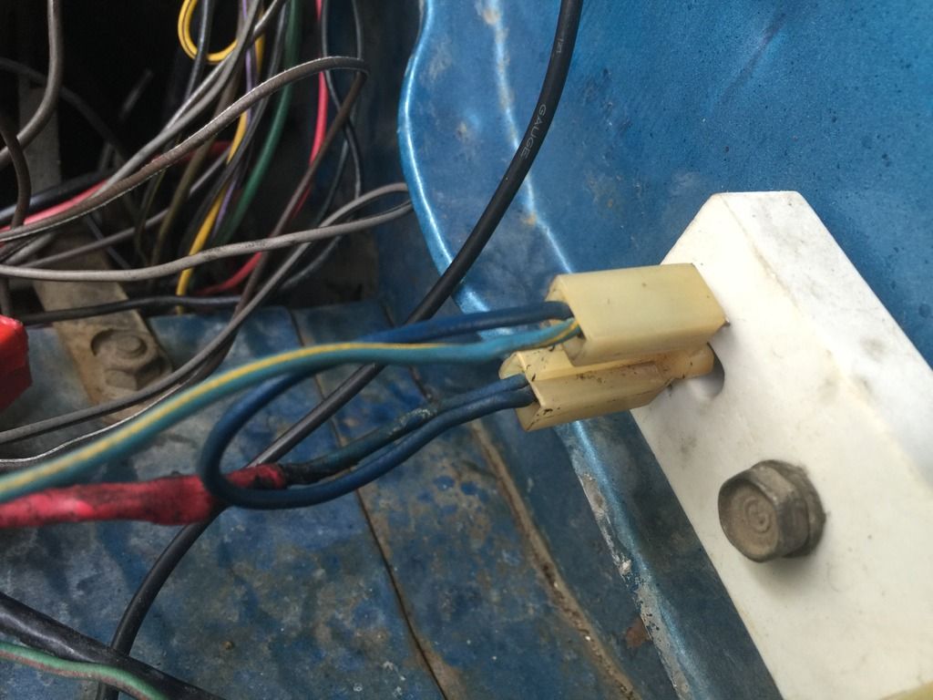
I have done the ammeter bypass and also bypassed the bulkhead connector for the ignition circuit.
After receiving Trailbeast’s HEI kit yesterday (and before installing), I decided to check for voltage drop in my ignition circuit.
With key in Run (engine off), I measured from Battery Positive to Voltage Regulator and got .7 volts.
It’s my understanding from other posts here that I am looking for .3 volts or lower.
My questions are:
WHERE DO I GO FROM HERE?
How to test ignition wire path on the engine side?
Should I ohm out each ignition wire path, and if so, what values am I looking for to determine GOOD vs. BAD?
Should I just start replacing the wires for the engine side ignition circuit? (read on below…)
Some things worth mentioning:
· Inside my car, my aftermarket volt gauge reads ~14.2.
(I have added a ground wire from voltage regulator to battery negative post. I have also added a ground from the stock electronic ignition box to battery negative post)
· I’ve noticed that when the car is running, I can pull the parking lights on and the voltage stays the same and the lights are ok but, once I turn on the actual headlights, the lights get brighter with the accelerator (I know the parking lights and headlights are on different paths).
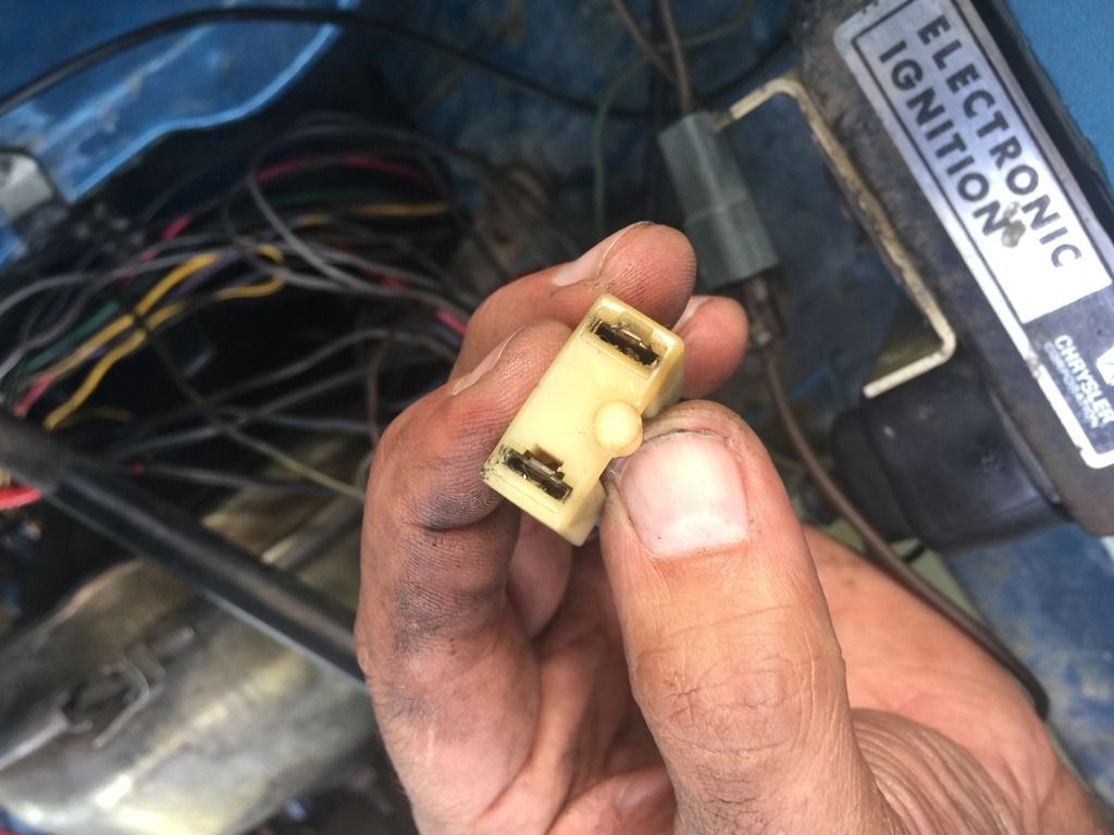
· I have also noticed that my engine side ignition circuit is pretty heavily band-aided together with much of it soldered/spliced at different areas. Isn’t it true that TOO MUCH solder can actually harm the circuit by causing resistance? I’m wondering if I should try making crimp connections instead.
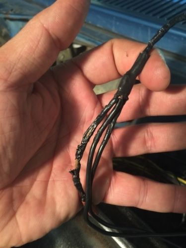
· One thing I noticed last night is, one of the wires (black with yellow tracer, I believe), going from the coil to the stock electronic ignition connector, has some heat shrink tubing over areas of the wire where the original wire insulation burned out (I verified this by removing a section of said heat shrink). It looks like this was a previous “quick fix”, without actually repairing the wire. I’m guessing that I may find more like this……


