Ignition Circuit Voltage Drop…where to from here?

-

Saverio

Well-Known Member
Joined
Apr 7, 2014
Messages
252
Reaction score
9
Location
nj
Car is a 74 Scamp w/ a 318.

I have done the ammeter bypass and also bypassed the bulkhead connector for the ignition circuit.

After receiving Trailbeast’s HEI kit yesterday (and before installing), I decided to check for voltage drop in my ignition circuit.

With key in Run (engine off), I measured from Battery Positive to Voltage Regulator and got .7 volts.
It’s my understanding from other posts here that I am looking for .3 volts or lower.

My questions are:

WHERE DO I GO FROM HERE?

How to test ignition wire path on the engine side?

Should I ohm out each ignition wire path, and if so, what values am I looking for to determine GOOD vs. BAD?

Should I just start replacing the wires for the engine side ignition circuit? (read on below…)

Some things worth mentioning:

· Inside my car, my aftermarket volt gauge reads ~14.2.

(I have added a ground wire from voltage regulator to battery negative post. I have also added a ground from the stock electronic ignition box to battery negative post)

· I’ve noticed that when the car is running, I can pull the parking lights on and the voltage stays the same and the lights are ok but, once I turn on the actual headlights, the lights get brighter with the accelerator (I know the parking lights and headlights are on different paths).

· I have also noticed that my engine side ignition circuit is pretty heavily band-aided together with much of it soldered/spliced at different areas. Isn’t it true that TOO MUCH solder can actually harm the circuit by causing resistance? I’m wondering if I should try making crimp connections instead.

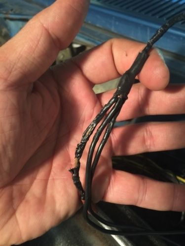
· One thing I noticed last night is, one of the wires (black with yellow tracer, I believe), going from the coil to the stock electronic ignition connector, has some heat shrink tubing over areas of the wire where the original wire insulation burned out (I verified this by removing a section of said heat shrink). It looks like this was a previous “quick fix”, without actually repairing the wire. I’m guessing that I may find more like this……
 
GOOD that is "well done" solder splices are not the problem

"Generally" just follow the circuit and check wherever you can "get to it."

Your likely suspects are the bulkhead connector, the ignition switch connector, and the ignition switch contacts themselves

One way to "work around" the problem is to relieve the switch of load and use the "ignition run" contact to activate a Bosch style relay, and use THAT to supply your ignition loads.

So....get to test points "where you can

Get a long wire and hook to battery positive, and one voltmeter terminal, so you can "move" your meter.

With key in "run"

Probe the engine bay side of the bulkhead connector on the "ignition run" line and confirm what that is. That reading should be VERY close to the highest drop, same as you measured. "Wiggle" that and see if it changes

Next move to the ignition switch connector. Check the battery "hot" line coming in against the "ignition run" line "coming out.

That right there should tell you a lot.

If the one coming "out" on ignition run is quite different reading from the engine bay side of the bulkhead connector, then the problem is in the bulkhead connector. All that "is there" is a short length of wire and the connector itself.

And, obviously, if the battery line going "into" the switch connector is quite different reading from the "ignition run" then it's right there in the connector and or switch.

Keep in mind these drops "add up" and they can CHANGE depending on "wiggle" and that includes the switch contacts, IE you might have 1/2 volt in the bulkhead, .3 in the two switch connections, and another "few tenths" in the switch contacts

And I hope you understand this is "load driven." More amperage on the load side means more drop. If you unplug the alternator field, the drop will decrease. This ALSO means that the more accessories that you attempt to add on the "run" line, the more drop you will have
 
Ok, did some measuring and I think I found what you pointed out.

I bypassed the bulkhead connector and replaced the ignition switch at the column about a year or two years ago when I did the ammeter bypass.

Measurements made with key in RUN, and engine off:

1. Battery+ to IGN1 at ballast (bottom left, from firewall) = .6 volts
2. Battery+ to IGN1 at ballast (top left, jumpered connection, to EI connector) = 1.0 volts
3. Battery+ to blue wire at alternator = .5 volts

Does it seem like my problem is linked to the connection at the ballast?

I did notice that, even with the key in run - the ballast resistor was getting hot (is that normal?).


Ballast hot is normal.

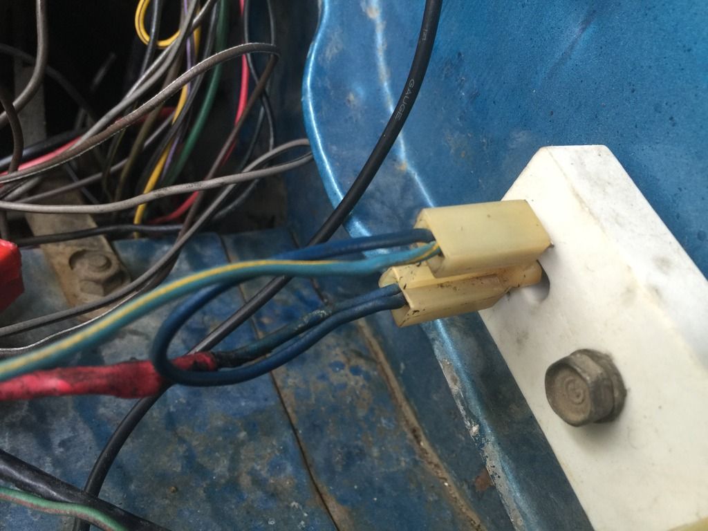
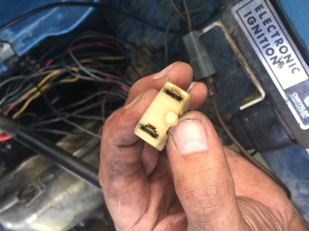
I forgot "one other place" Does your car still have the WHITE connector in the harness from the firewall to the engine? That might be a factor.

In your measurements, no1 and no3 are probably electrically the same point.

That is, voltage comes out the firewall, and branches off at some point. Without stripping the harness and examining it, I would not know exactly where that is.

Given your measurements, I would bet on ignition switch / connector

Now you say you bypassed the bulkhead, but did you bypass EVERYTHING or only the red and black ammeter circuit? The ignition circuit terminals in there (IGN1) could still be a factor.
 
Ah yes, I know of this white connector you speak of. Wanna know how? LOL. When my alternator shorted out (you might remember that fiasco), it fried the ignition wire and that white connector. I had no choice but to drill out and bypass that connector when I rewired.

Yes, when I bypassed the bulkhead I bypassed the alternator wire as well as the ignition wire. I just checked and The only wires left on that connector are the starter relay and temp sending wire.

So it sounds like I now need to move inside the car, under the column and check the wires/connectors there?
 
With key in Run (engine off), I measured from Battery Positive to Voltage Regulator and got .7 volts.

You're right, that's higher than you want (but it's also typical-to-low for these cars of this age). An ignition-loads relay, already suggested, is a very good idea (if you put it together neatly and thoughtfully with good-quality parts) that will eliminate the need to chase down where the voltage drop is in the existing circuitry, because all the ignition switch and its wiring will be doing is triggering the relay—and relays take very little power to trigger.

(I have added a ground wire from voltage regulator to battery negative post.

Good. Complete the ground ring with a wire from the alternator housing to the voltage regulator base. Many alternators have a round "GRD" hole on the back half of the housing. Use a self-tapping screw to secure a wire to it—make it a short one; a long screw could hit the rotor and ruin things.

I’ve noticed that when the car is running, I can pull the parking lights on and the voltage stays the same and the lights are ok but, once I turn on the actual headlights, the lights get brighter with the accelerator

This may improve to some degree when you add the regulator to the ground ring. Various degrees of weakness at idle is common with these alternators; given that you've bypassed the ammeter (assuming you've created an adequate and safely protected power path from alternator output to battery +) you can install an alternator with better output characteristics. Lots of choices; that's kind of a separate discussion topic. Note that the remanufactured and "upgraded" original-style alternators you can buy at parts stores may have higher peak current output, but tend to have poorer-than-stock low-RPM output.
 
Good. Complete the ground ring with a wire from the alternator housing to the voltage regulator base. Many alternators have a round "GRD" hole on the back half of the housing. Use a self-tapping screw to secure a wire to it—make it a short one; a long screw could hit the rotor and ruin things.

Hey Dan, thanks for your info! I went ahead and added this ground like you suggested. My alternator actually had a GRND screw marked on it!
I am leaning very heavily on adding an igniton-loads relay.

Note that the remanufactured and "upgraded" original-style alternators you can buy at parts stores may have higher peak current output, but tend to have poorer-than-stock low-RPM output.
Speaking of remanufactured alternators...when I replaced my old one that shorted out, I was in a bind and...you guessed it, had to buy a remanufactured one from Advance Auto.


Oh, now check this out...


Del must really know his stuff - suspecting the ignition switch. I should also mention that when my first alternator fried, it burnt the wires all the way up to the switch, so I also do NOT have an ignition switch connector. All that is now hardwired.


A funny thing just happened...I went and fired up the car and noticed the key/switch felt funny. I BARELY touched it and went backwards out of RUN and turned off!

It seems like whatever "stop" (inside the switch), that was in place to differentiate between ACC/RUN/START is completely gone. What the hell?? What are the chances?! Oh well, better in my driveway than on the road I guess!

Well, looks like I'll be replacing the ignition switch, again. This will be the 2nd in 2 years, and I got this previous one from NAPA.

I really wonder now if this was the cause of my issue.
 
It's getting harder to buy good-quality parts for our cars. Yes, you can still get a new ignition switch…in finest Chinese "quality". Fortunately there are still stashes of NOS American-made parts that don't necessarily cost a fortune, such as at Old Car Parts Northwest (call rather than email for fastest service).
 
If you replace the ignition switch check the circuits thru it. I had a new standard ignition I installed in my Demon while redoing the column. Would crank and start but died as soon as it returned to run. Found the switch to be open in run. Had to tear back into it to replace it again.
 
If you replace the ignition switch check the circuits thru it. I had a new standard ignition I installed in my Demon while redoing the column. Would crank and start but died as soon as it returned to run. Found the switch to be open in run. Had to tear back into it to replace it again.

Wow that really sucks! I'm glad you mentioned it, I was just eyeing a Standard Switch on Summit. Checking ebay, I see there are a couple OE switches for about the same price.
 
Relays are your friend. If you relay the headlights, and also the ignition (the high load items), it takes a TON of load off that ignition switch. Also, I suggest bypassing the amp meter and using your starter relay B+ post as your load center.
 
Also, I decided to check the IGN1 circuit from the firewall and unravel all the surprises that awaited me! Check this out - the charred wire is the path to the voltage regulator. Possibly yet another reason for my voltage drop?

Needless to say, I'm going to rewire that entire circuit from the firewall to every path it branches off to in the engine - maybe i'll use a larger gauge wire while I'm at it.


Hmm... that looks nice! I'd keep the same gauge or only one step larger; the wire is not usually the issue; the connections and crimps on the wire ends are.
 
Hmm... that looks nice! I'd keep the same gauge or only one step larger; the wire is not usually the issue; the connections and crimps on the wire ends are.

Thanks for the tip!
You're right, I think What I actually read/saw was people using a large gauge for the alternator output to starter relay connection (8 gauge I believe) ... Not a larger gauge for the VR connection. 👍🏽
 
Well guys, I got all my spark plug wires changed, rewired the entire IGN1 circuit, installed the Classic HEI Kit from Trailbeast (with a relay for the coil) and my voltage drop is now reading 0.2, steady.

I still have to replace my ignition switch but, I think I got it fixed!
 
-
Back
Top