4mulaSvaliant
Well-Known Member
OK so I am doing this so it will maybe help a few other 69 owners since our ignition switch is a one year only item. I recently needed to replace and found it to be worth more than I wanted to pay not to mention I would have to re-key either the ignition or my door locks since my lock cylinder was worn badly as well.
Anyhow here is a step by step process as to how I went about it. If nothing else, it shows what it looks like inside the "non service-able" ignition switch.
Here goes, now lets see if I can post and narrate worth a darn.
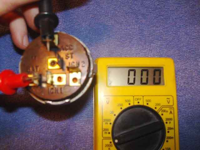
Ok so Im assuming you can get the switch out, so I will start with how to get the "switch" part away from the pot metal housing. I used a flat tip screw driver to VERY carefully bend the 4 retaining tabs away from the black plastic.
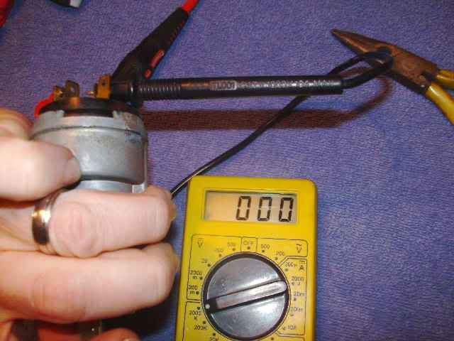
I ended up using a pretty small but strong screw driver and actually broke the tiny stamped marks, which were actually the part that was retaining the black plastic. However you do it, proceed with caution! If there is a place that the rebuild will fail.......This is it! Break these and the housing is basically worthless.
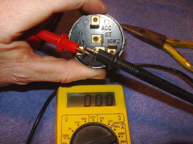
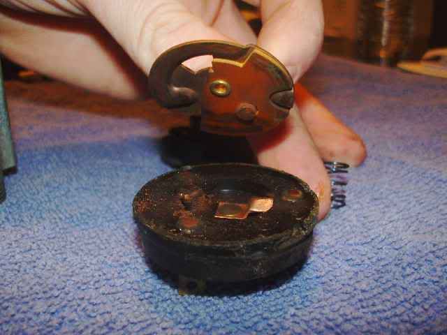
In the picture below you can see the little indention's that actually were broken out / removed. It happened by accident when prying, but worked in my favor. Im sure this will be the norm when taking it apart.
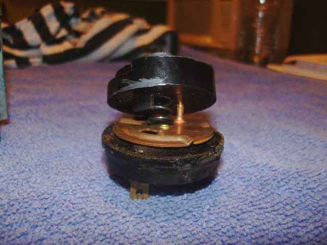
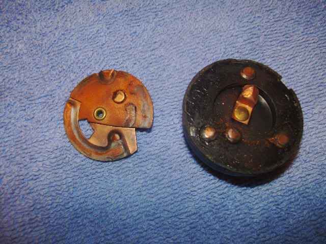
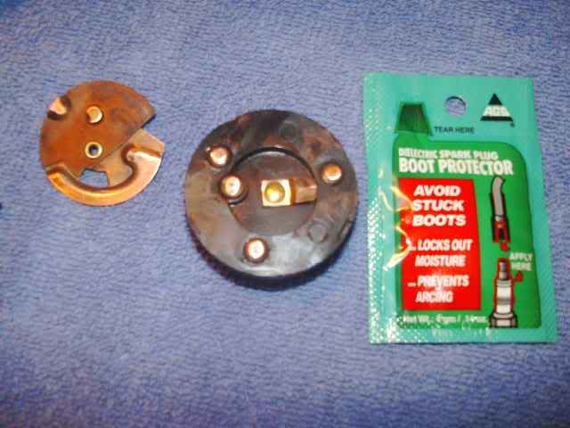
Here are the parts that you will discover after freeing the black plastic from the pot metal housing. As you can see there is one spring in this assembly. It is very easy to locate where it goes if you happen to let it fly when you take it apart.
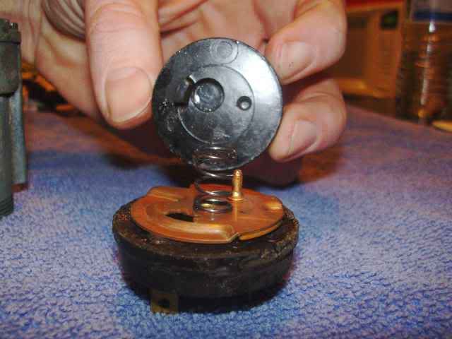
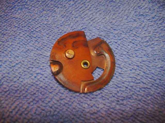
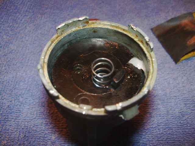
Here is the side that makes contact with the actual lock cylinder. You can only see the center when the housing is all together. The spring you see here is stuck in place and shouldn't fall out on its own.
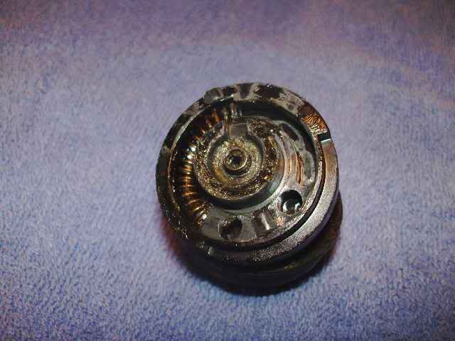
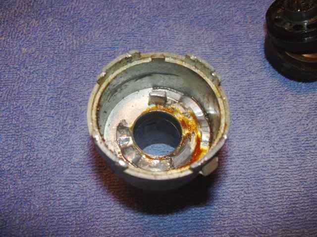
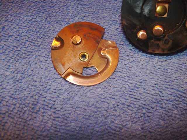
Next is the "contact" part of the switch. This is the dirty, and worn area that has caused me my intermittent issues. Check out all the shavings from 41 years of key twisting.
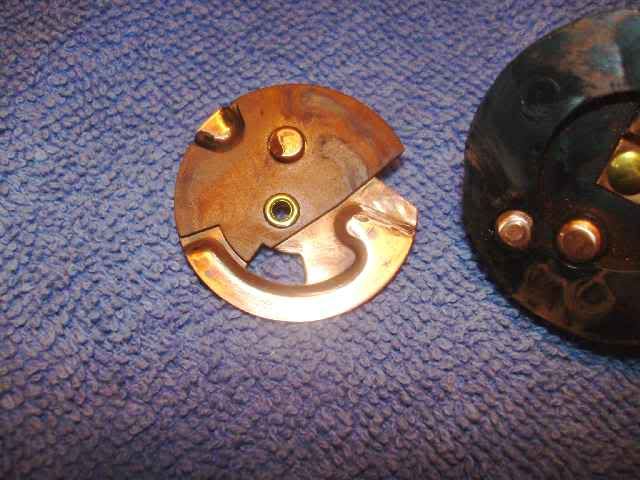
Here are the parts with a little cleaning. I used some very fine sand paper, and was done in a matter of seconds. There are chemicals that are great for cleaning brass, but I used what I had and what is simple.
Chowder my 1 year old Yellow Lb telling me this is boring!

Had to throw in his decent shot too! LOL

Ok so now on to the reassembly. I was very liberal with Di-electric grease. Use the crap out of it! Its not going to hurt anything, and enough to do the job is in ONE of the packets you can get for spark plug wire sets.
With the housing pointed down, I dropped the first piece in with the spring and of course applied some electric grease to aide in keeping my repairs lasting.
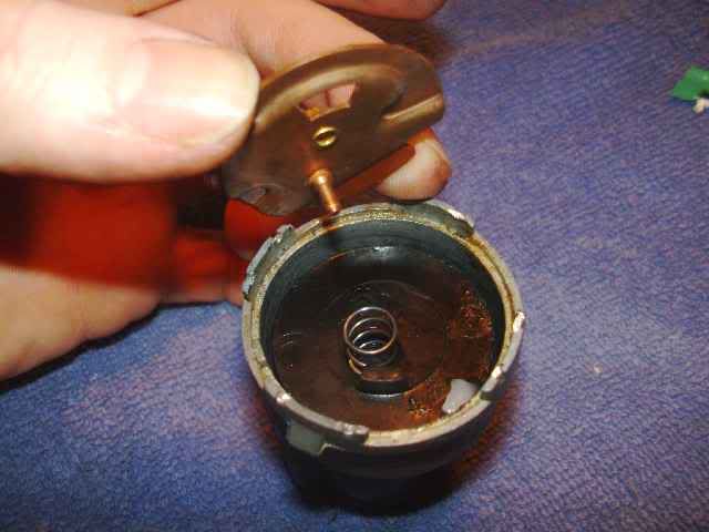
Next is the copper contact plate. This only goes in one way. Now the spring will hold it from sitting in a helpful position, but it will be stable enough to stay put.
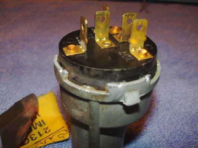
The last part to install is the black plastic piece that the actual harness plugs into. This piece is keyed to the housing and can only go in one way.
It is now possible to take a hammer (carefully)to the 4 retainer tabs that hold it all in place. Because the black plastic is a tight fit, you wont need to move the tabs inward very much to have a good snug fit again. Above it was accomplished with a small tap to each corner of each of the 4 tabs.
Hope this helps.
Thx guys and gals!!!!:cheers:
Anyhow here is a step by step process as to how I went about it. If nothing else, it shows what it looks like inside the "non service-able" ignition switch.
Here goes, now lets see if I can post and narrate worth a darn.
Ok so Im assuming you can get the switch out, so I will start with how to get the "switch" part away from the pot metal housing. I used a flat tip screw driver to VERY carefully bend the 4 retaining tabs away from the black plastic.
I ended up using a pretty small but strong screw driver and actually broke the tiny stamped marks, which were actually the part that was retaining the black plastic. However you do it, proceed with caution! If there is a place that the rebuild will fail.......This is it! Break these and the housing is basically worthless.
In the picture below you can see the little indention's that actually were broken out / removed. It happened by accident when prying, but worked in my favor. Im sure this will be the norm when taking it apart.
Here are the parts that you will discover after freeing the black plastic from the pot metal housing. As you can see there is one spring in this assembly. It is very easy to locate where it goes if you happen to let it fly when you take it apart.
Here is the side that makes contact with the actual lock cylinder. You can only see the center when the housing is all together. The spring you see here is stuck in place and shouldn't fall out on its own.
Next is the "contact" part of the switch. This is the dirty, and worn area that has caused me my intermittent issues. Check out all the shavings from 41 years of key twisting.
Here are the parts with a little cleaning. I used some very fine sand paper, and was done in a matter of seconds. There are chemicals that are great for cleaning brass, but I used what I had and what is simple.
Chowder my 1 year old Yellow Lb telling me this is boring!
Had to throw in his decent shot too! LOL
Ok so now on to the reassembly. I was very liberal with Di-electric grease. Use the crap out of it! Its not going to hurt anything, and enough to do the job is in ONE of the packets you can get for spark plug wire sets.
With the housing pointed down, I dropped the first piece in with the spring and of course applied some electric grease to aide in keeping my repairs lasting.
Next is the copper contact plate. This only goes in one way. Now the spring will hold it from sitting in a helpful position, but it will be stable enough to stay put.
The last part to install is the black plastic piece that the actual harness plugs into. This piece is keyed to the housing and can only go in one way.
It is now possible to take a hammer (carefully)to the 4 retainer tabs that hold it all in place. Because the black plastic is a tight fit, you wont need to move the tabs inward very much to have a good snug fit again. Above it was accomplished with a small tap to each corner of each of the 4 tabs.
Hope this helps.
Thx guys and gals!!!!:cheers: