Painless wire harness install (MORE PROGRESS)

-

younggun2.0

Well-Known Member
Joined
Jan 27, 2012
Messages
4,793
Reaction score
1,515
Location
federal way, wa
Started with the install of a painless universal wire harness today. My original harness was chopped beyond repair by the previous owner. The kit i am using is Painless part # 10307. It is a universal harness designed for street rods and customs with limited circuits. My car has an MSD ignition and distributor, no wipers, no heater, no radio and an aftermarket dash with mechanical gauges. I am using the suggested GM wiper switch (more on that later) and re-using my factory keyed ignition. The kit is designed to be used with a GM steering column.

I cut off the factory steering column pig tail and installed a universal 8 pin connector.

here is what i started with.
newwires001-1.jpg


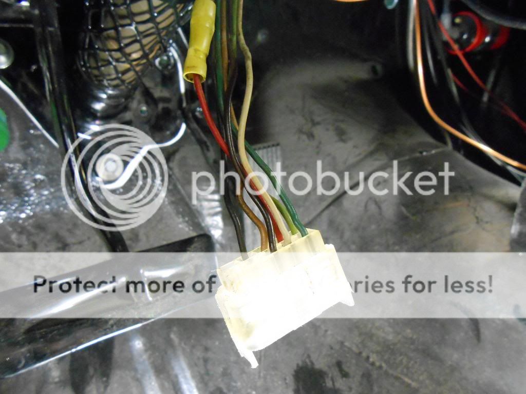
then i crimped on my new ends.
newwires002-1.jpg


here is the new connector installed with heat shrink on the wires.
newwires003-1.jpg


Next I installed the head light switch in the dash. I modified the factory bezel from my mopar switch to fit the new switch. Once i change the knob you will never know that i used a GM switch.
newwires004-1.jpg


newwires005-1.jpg


I finished the night working on my mounting point for the fuse panel. I am going to be mounting it on the driver side kick panel area. it will go on the wall that the air box used to be. here is the mount that i made. it is not finished and will have a bracket that bolts onto the fire wall.
newwires001.jpg


newwires002.jpg


newwires004.jpg


newwires005.jpg
 
today i decided to remake my fuse panel mount. the first one was a bit sloppy and pretty heavy. here is the new mount.

newwires003-2.jpg


newwires004-2.jpg


and here it is mounted up in the car.

newwires011.jpg
 
for a wire harness install i haven't done much wiring. ha ha ha. trying to get everything mounted in its home before i run all the wires.
 
what crimpers are you using for the terminal blocks and do you like them
 
Why are there so few fuses? Are you using an auxiliary relay/ fuse box under the hood?
 
what crimpers are you using for the terminal blocks and do you like them


Tool Aid 18960 Quick Change Racheting Terminal Crimping Kit

by [ame="http://www.amazon.com/s/ref=bl_sr_automotive?_encoding=UTF8&field-brandtextbin=Tool%20Aid&node=15684181"]Tool Aid[/ame]

i love them. they make it impossible to under/over crimp my ends. i was turned onto these from ABODYJOE. they cost 75 bucks to my door.
 
Why are there so few fuses? Are you using an auxiliary relay/ fuse box under the hood?

I am using the 8 circuit universal harness # 10307 from painless. It is a very basic kit. I have no heater, wipers or stereo. I also have after market mechanical guages and a complete MSD ignition system. the only thing i really need is my lights/signals,charging system and ignition system. My car is about as basic as it gets. I will have 3 accessory circuits open on my fuse block. this harness is also modular and i can expand easily if i so desire down the road.

I plan to run a power and ground wire from the battery (in trunk) to a "terminal junction box" up under the dash. This way i can run power to my fuse block and my msd ignition box up (under the dash) and not have to run multiple power leads to the post on my starter relay.
 
I think you mentioned that. The old man spaced it out. LOL
 
while i have your attention....... my ignition switch has 2 12ga wires going into the "battery terminal" on my ignition switch. the wires come straight from the fuse box to the switch. they are both labeled identically (#934 b+ ignition switch). my guess is that these wires are to be attached together to handle the load of all the accessories that will take power from that source? I called painless and mentioned that to the tech. and he ran with that idea but didnt seem very sure.
 
while i have your attention....... my ignition switch has 2 12ga wires going into the "battery terminal" on my ignition switch. the wires come straight from the fuse box to the switch. they are both labeled identically (#934 b+ ignition switch). my guess is that these wires are to be attached together to handle the load of all the accessories that will take power from that source? I called painless and mentioned that to the tech. and he ran with that idea but didnt seem very sure.

I would venture to say YES also. B+ is B+. Be sure when you solder them together that you double over the soldered joint with 2 layers of Heat Shrink on those wires!! I actually try to do that on all my soldered connections if possible. The second piece I cut a little longer than the first.
 
So what did that wire kit set you back??? Looking to do mine
On my dart.
 
i got it from summit racing. i had a credit on my accnt. they also had a free shipping deal going. they retail for 300. i got the new gm headlight switch too. they are 50. i paid 75 for my crimpers, 100 for a heat schrink/solder crimp fittings kit and another 20 on a kit of heat schrink tube. im guessing that i will have about 800 in the whole project when done. but that will be all new wiring and switches for the entire car. well worth it if you ask me.
 
I would venture to say YES also. B+ is B+. Be sure when you solder them together that you double over the soldered joint with 2 layers of Heat Shrink on those wires!! I actually try to do that on all my soldered connections if possible. The second piece I cut a little longer than the first.

just got off the phone with another tech that knows his ****..... the harness comes with 2 of the power wires to the switch because some ignition switches use two power leads. he said that the one wire is plenty but i can also splice them together. so i will be heat shrinking them all the way back to the fuse block and connecting them at the switch.

"B+ is B+" reading that makes me see it now. it comes from and goes to the same location, has to be put together.
 
tonight i got the passenger side mount finished up. I am mounting a power supply and ground junction box that will supply power/ground to my MSD box and my fuse panel as well as a couple other circuits. It will also mount my starter relay and voltage regulator.Made the box out of 1/16 in steel and then made a carbon fiber face plate. here it is guys. just have to powder coat the base and then mount it up in the passenger side upper kick panel area.

junctionbox001.jpg


junctionbox002.jpg


junctionbox003.jpg


junctionbox004.jpg


junctionbox005.jpg
 
i really enjoy fabricating stuff. i am trying to keep the engine bay pretty much wire free. i like the look of a clean clutter free engine bay. hopefully this all works how i have it planned in my head.
 
In some cases you will find the seperation occurs in the fuse box. So a group or section of fuses on each of the wires. That only improves safety. Catastrophic failure of one doesn't take out all of them. Example.. front end collision takes out headlight circuit all the way to the ignition switch yet dome lamp and brake lamps live on. Hope that makes some sense.
 
In some cases you will find the seperation occurs in the fuse box. So a group or section of fuses on each of the wires. That only improves safety. Catastrophic failure of one doesn't take out all of them. Example.. front end collision takes out headlight circuit all the way to the ignition switch yet dome lamp and brake lamps live on. Hope that makes some sense.


this has me confused..... are you saying that the fuse box already separates my circuits so i don't need to seperate my power supply from the starter power post with my junction box? I am running the separate junction boxes for power and ground to the under side of the dash in order to 1.) eliminate the wires going thru the fire wall 2.) running a ground junction box that is wired directly to the battery negative terminal eliminates the chance of bad chassis grounding. This is all in an effort to keep as much hidden as possible.
 
I can't know how the fusebox is made inside or why. Most have several seperate buss bars with their seperate power supplies even though more than 1 of those power supplies originates at the same source. The why can be related to wire gauge just as others have suggested.
I'm fairly good at figuring out the OEM methods to the madness but honestly..
Idont know squat about aftermarket wiring.
 
The short answer is, the painless book should have a chart that shows the origin of each numbered wire. They don't bother to give you a wiring diagram.

I downloaded the manual, here

[ame]http://www.painlesswiring.com/Manuals/10307.pdf[/ame]

The chart on page 26/27 (manual page numbers, not viewer page numbers) shows only one listing for #934, originating at the fuse panel. I would guess that they are both paralleled and that they are not fused.
 
you are correct. both #934 wires are coming out of the same terminal on the back side of the fuse box . the tech. at painless told me that some ignition switches call for 2 power leads to the ignition switch. mine only calls for one. I have simply shrink wrapped both wires together all the way back to the fuse panel and crimped them together as 1 wire on the ignition switch side. this wire is not fused like you said.
 
another question.....

I have my battery positive wire going to the starter bat + post. usually you would have another wire that would go from the starter bat+ post to the starter relay bat+ post. then you would have your alternator charge wire going to the post on relay.

why do all the bat+ wires have to meet at the starter relay?

can i run my battery wire to the starter post. then the alt. charge wire to the starter post?

then run my power from the battery to the fuse box directly, skipping the starter relay?

then run my power from battery to starter relay post?

the reason i ask is that i have the starter relay mounted up under the dash. I also have a battery power junction box mounted up under the dash board. the junction consists of a 8ga. wire from the battery in the trunk to the junction box up under the dash. that is what i plan to use to power the fuse panel (with fuse inline)and my msd box.

why do all the bat+ wires have to meet at the starter relay? They Don't

can i run my battery wire to the starter post. then the alt. charge wire to the starter post? YES

then run my power from the battery to the fuse box directly, skipping the starter relay? YES However on some Fuse Boxes like stated earlier, may be ignition enabled "Made hot by the key", I don't believe that is your situation here

then run my power from battery to starter relay post? YES
 
-
Back
Top