This is the second stage for assembling the engine... In this chapter I am going to go through installing the crankshaft and checking the bearing clearances with plastic gauge...
This is the next step to continue after Sections 1 - 4 where we tore the block down and cleaned it up, then put the cam bearings, freeze plugs, and oil galley plugs in, and verified everything was done correctly... If you missed them, you can find it here...
How to Rebuild a Small Block Part 1: Block Prep
How to Rebuild a Small Block Part 2: Cam Bearing Install
How to Rebuild a Small Block Part 3: Install Water Jacket and Oil Galley Plugs
How to Rebuild a Small Block Part 4: Pre Flight Inspection After Machine Shop Before Assembly
*************************************************************************
Hello everyone, it's Krazykuda here to show you how to rebuild a small block... This article is to help any newbies through rebuilding a small block Mopar LA engine, but may have a few tips that some of you seasoned builders may find useful... If you haven't ever built an engine, I will show you what you need to know to do it yourself...
The goal of this series is to show what you can do at home in your own garage... Go at your own pace and ability and then take it to someone knowledgeable for what you are not capable of doing yourself or don't have the proper equipment/tools for...
Keep checking back in from time to time as this is a work in progress and I plan to keep updating it as I build more engines and can show you more variations...
I am going to break this into sections that you can follow along with and make sense to do in 'stages' when you build... Plus you can then jump to the section that you are working on to help keep from sorting through one very long thread to find what part that you are working on when you are doing it....
*************************************************************************
*** Important Note *** Sometimes things may not go right and you will run into a snag/road block... Do not get in a hurry to finish and take short cuts that may compromise your build...
Step back, take a break, and think about it for a while... Or seek help from other experienced people or professionals to overcome the problem... Do it right and don't take any unnecessary chances that may compromise the integrity of your build...
If you don't fix the problem correctly, it may come back to haunt you and cost even more time and money than if you took the time to think about it and research it to fix the problem correctly...
This has been a public service announcement from krazykuda....
*************************************************************************
Get a good set of taps and dies:
The first thing to do before installing the crankshaft is to chase all the threads in the block... This will ensure that all of the threads are true and clean... You won't believe some of the build up that you can find in the holes... By re-tapping the threads, you can remove any distortion of the metal of the threads and clean out any of the dirt and muck that has built up over the years or any that settled in when hot tanking or cleaning the block...
You can buy the taps separately, or get a nice kit... I have a nice tap and die kit that I bought at my favorite local Ace Hardware store in Homer Glenn, IL which is not far from me... There are some stores closer to me, but this place is worth the trip for the hard to find items... I like this store because they carry many hard to find items that most other hardware/home improvement stores do not... Most stores only carry taps and dies up to 1/2" where this place stocks them up to 3/4" at least, maybe even larger... Plus they are the only store that carries the kit that I like that goes up to 1/2"...
Will Cook Ace Hardware, Homer Glen, IL, 60491
I used Craftsman taps back in the 80's and they were junk... I once broke 3 taps in an oil pan rail on one block and had to use 3 Helicoils to fix them and then swore never to use Crapsman taps again... I found the Irwin/Hanson taps and dies to be much better and have been using them ever since...
Here's my old 'trusty' kit that has a few missing... You can see that it's had its share of use...
However I buy extra singles of the most popular ones and keep them in my main tool box... (I keep most of my good tools in there so my kids don't get into them and loose them on me)...


Here's my spare complete kit that I keep locked in my file cabinet in my room that I use in emergency...


This is my favorite go-to tap wrench that I like from the kit... It's good for taps 5/16" and larger... The smaller one in the kit is best for the 1/4" and smaller taps... I like this wrench as it has the square drive in the end that you can use a 3/8" ratchet and extension in...


Here it is with a ratchet...

Here's the standard straight tap wrench that will fit any tap... One side of the handle screws in and out to install and remove the tap... The one thing that I don't like about this tap wrench is that sometimes the handle turns while you are using it and it loosens the grip on the tap and you have to keep tightening it...


Some people recommend using bottoming taps to clean out the holes, but any standard tap will do... The important thing is to remove any deformed part of the thread and make it true again... It's harder to find bottoming taps vs standard taps... Standard taps will get the job done and be more affordable...
*************************************************************************
Tapping all threads in the block:
Always chase the threads with a tap before assembling your parts... Always, always, always...
Then always tighten the bolts to the proper torque called out in the service manual...
This will make sure that you have the proper clamp load on the part and it will not loosen later... The torque specs were developed for a reason, if they were not important, they would not take the time to develop them...
By chasing all the threaded holes in the block, you will have clean threads so you will get the proper clamp load for the specified torque for the bolt... Not to mention that the bolts will go in much easier and not bind... It's nice when you can thread the bolt most of the way down the hole with your fingers vs having to use a wrench to screw them in... It will also be much easier to take apart if you need to do any repairs later... It's time well spent as it will save you trouble tightening the bolts...
You can go a little further when using standard taps, and maybe go a little deeper as when you machine tapped holes, you drill the hole about 1/4" - 3/8" deeper than the tap depth (depending on the diameter and depth of the thread)... This is "chip allowance" and prevents the chips made from tapping the hole from filling the bottom of the hole and the new chips have nowhere to go, so the tap will then break... As you cut the threads with a tap, they make chips when they form the threads.... Some of the chips go into the flute of the tap and some fall to the bottom of the hole... If the bottom of the hole gets filled with chips before the thread is done, it can bind the tap and cause it to break...
First we'll start out with the rear of the block and do the transmission bell housing attaching threads... They are 3/8" - 16 (3/8" coarse) threads.... I like to do these first as they are used to mount the engine to the engine stand and you want good clean threads to hold your engine while you are building it...


Go in until you feel the tap bottom out... It takes a little bit to get the feel of the taps and learn how far you can "push" it before the tap breaks... When it bottoms out, give it a quick medium 'tug' to make sure that it's fully bottomed out...

Here you can see some of the crud that accumulates in the holes... Clean the tap with a shop rag going down each of the flutes of the tap to remove the crud after tapping each hole... If you get alot of crud from one hole you may want to chase it again after cleaning the flutes of the tap... Sometimes it takes two or three times to remove all of it in a very dirty hole...


This crud will cause the bolt to bind and will not give the proper clamp load for the specific torque that you tighten the bolts to... 85% of the torque is influenced by the surface friction on each thread and the surface under the head of the bolt... Any foreign material/crud will cause the bolt to bind and not let the bolt reach proper clamp load for that specified torque...

I like to blow any debris out of the hole with compressed air first to get the dry loose stuff out...

Then take some parts cleaner with the straw attached to it and blast out any wet/hard to get debris... Stick the straw all the way down the hole until it bottoms out, then back off about 1/8" or so and give it a blast to wash out any hard to get crud to back wash it from the bottom out... By sticking the straw almost to the bottom of the hole, you flush out the debris instead of putting the tip of the straw at the beginning of the hole and blow it back in...
Be careful for any spray back and wear safety goggles to prevent the backwash from getting in your eyes....


Then give it one more blast of compressed air to remove any remaining debris that may be left in the hole...

Then after putting the block on the engine stand, move onto the bottom of the block...

The main bearing cap threads are 1/2" - 13 threads (or 1/2" coarse thread)... The 1/2" stands for the diameter of the outside edges of the threads, and the 13 stands for the pitch of the thread that tells how many threads per inch for that tap...

Then move on to the oil pan threads which are a 5/16" - 18 thread (or 5/16" coarse thread)...

Then the oil pump attaching threads in the top of the rear main bearing cap take a 3/8" - 16 (3/8" coarse) thread....


Then move onto the left/driver's side head bolt threads.... They are also the 1/2" - 13 coarse thread...


Then do the passenger/right side head bolt threads... Also a 1/2" - 13 coarse thread...


Now move onto the front of the block...

Get the timing chain cover and water pump attaching bolt holes.... They are 3/8" - 16 coarse thread....

Next go onto the camshaft thrust plate bolts which are 5/16" - 18 coarse thread...

Then while you have the 5/16" - 18 coarse tap loaded, then move onto the top of the block and tap the distributor hold down bolt hole....


Then chase the oil sending unit/oil pressure gauge hole threads... These are 1/8" pipe thread... Be careful with tapping pipe threads as the pipe taps are usually tapered... If you tap them too deep, the hole can get too big and the sending unit/ pressure gauge adapter will bottom out before it's tight and will leak... Go until it gets tight and then stop, don't push it like you can with regular taps....
At the engine factory, we used a straight pipe tap for the female hole, and then used a tapered pipe thread for the plugs... This way the hole is constant diameter and the plug acts as a wedge or cork to plug the hole... This method eliminates the potential of tapping the tapered hole too deep and is a more reliable way to seal the hole... However, it's difficult to find straight pipe taps and they will be more expensive...

There are also a couple of tapped holes in the side of the block for attaching the transmission braces, but in many applications they are not used, especially with headers, the header tubes usually block the path of the brace between the block and transmission mounting holes, so I don't pay much attention to them unless doing a complete restoration... You can tap them if you wish, but we've gotten all of the important holes for now...
Now that you've chased all the taps in the block, you are ready to start assembling parts into the engine...
*************************************************************************
Install the rear main seal:
If the old rear main seal hasn't been removed yet, remove it and clean up the groove that it goes into...


Take a flat blade screwdriver and remove any debris that is left in the groove... Then clean the groove with some parts cleaner and a shop towel to get it nice and clean...

My two favorite cleaners are Brakleen (the chlorinated works best) and Berryman B-12 carb cleaner... Barryman is good to get the black carbon soot off like what builds up on the carburetor etc... But my go-to cleaner is the CRC Brakleen as it cleans very well and dries faster.... The Berryman's has a strong smell and should be used in a well ventilated space...


Now take the rear main seal from the gasket kit... (I like to buy one of the Mancini Racing engine rebuild kits that come with bearings, rings, and complete teardown gasket kit which I will get into more in the next section when we install the pistons...)


Now that the rear main seal groove is clean, I like to put some clear RTV in the groove before installing the seal... My theory is that the RTV will give a little more pressure on the rear main seal as it wears to help keep it from leaking... It's worked well for me... But eventually as an engine gets many miles on it, the rear main seal will eventually start to leak... This trick helps it last a little longer before it starts leaking...
Here's the clear RTV that I like to use...

Here's both halves of the rear main seal from the kit...

Here's a closer view and notice that the inner lips of the seal has a knife edge on it... This edge goes toward the front of the engine...

Here's a closer view of the knife edge....

Here I have highlighted it in red....

Put a nice bead of RTV in the block groove for the rear main seal like this...

Then use your finger to smooth it out evenly like this...

Next install the rear main seal making sure to press it all the way into the groove... Some of the RTV will squish out, use your finger to remove the excess....

Now put a bead of RTV in the rear main bearing cap like with the block...

Smooth it out with your finger...

Press the rear main seal into the rear main bearing cap...

Smooth out the excess RTV with your finger....

*************************************************************************
Install the bearings:
You must be diligent to keep everything extremely clean when installing bearings... I use painter's tack cloth to clean up any lint or debris from the bearing surfaces where the back of the bearings seat... You must keep any lint or debris from getting on the surface of the bearing and back surface where the bearings seat... I've seen a spec of dirt or piece of lint or thread from a cloth make the bearings tight, or even lock up a crank completely... You must strive for perfection and get these surfaces hospital clean...
Here's some different brands of tack cloth that you can get... I recommend picking up a half dozen or more to build the engine as they are cheap enough... You can buy tack cloth at any hardware or home improvement store...


Here's the tack cloth opened up...

Clean the bore where the back of the bearings go before installing the bearing shell...

Then clean the back side of the bearing before installing it in the cap...


Here are the main bearings from the kit... Notice how most of them have holes in the center, except for the rear main bearing... Make sure that the ones with the holes go into the block to let the oil get into the main bearing holes that we probed in the last section (part 4)...

Here's the one without the hole... This one goes into the cap so it doesn't block the oil flow into the block...

Here's the other main bearings that have holes in both shells... These can go into the cap or the block... It doesn't matter if the cap bearings have the hole, but it's important to have the hole in the block side...

Here's the block showing the oil holes in the mains of the block...

Clean the main bearing bores with a tack cloth before installing the bearing shells...


Now put the main bearing shells in making sure that the ones for the block have the oil holes in them and the holes in the bearing line up with the ones in the block...

Line up the tab/anchor slot side first, then press the other side to seat the shell into it's seat.... Press on both sides to make sure that it's centered in the bore and both ends are even with the channel in the block bore...

The rear main shell in the block...

You may want to probe the block with the wire coat hanger to make sure that the holes are still open...

Now put the shells in the main bearing caps... The smaller shells go into the #1, #2, and #4 main caps... Wipe both the cap surface and back of the bearing shell with a tack cloth before mating them together....

The thrust bearing has more resistance to install as it has the flange on both sides... Line up the anchor slot side first, then press on the other side until you get it fully seated and both sides even with the bottom edge of the cap...


Note that on all of the caps except the rear main seal cap that there are numbers on one side and the letter "Z" on the other... The numbers should all be on the same side when they are all in the proper position...

Here the numbers are circled in red and the "Z" is circled in yellow....

Now wrap the tack cloth around each main bearing journal like this and go back and forth to clean any dirt and debris off of the main journals...

Repeat this for all 5 main bearing journals....

Here they all are circled in red....

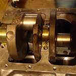
Now carefully install the crank into the block... You want to install the crank dry right now as the plastic gauge needs to be done dry without any lube to alter the readings...


Now line up the anchor slots/tabs on the cap and block to be on the same side so they oppose each other and keep the bearing from spinning... The number one cap goes on the first main in the front of the block and then put them on sequentially in order... You cannot mix and match the positions of the caps as they have to be mated to the same main as they were originally machined on... If you mix the caps to a different location than they were machined, there could be a mis-match in the bore enough to make the crank tight...

Here the anchor slot is circled on both the block and cap... Install these so they are together for each main bearing cap...

Here's another view of them...


Now after all of the main bearing caps are in position, look at the markings on the cap and verify that the numbers are in sequence starting with #1 in front and increasing as you go toward the back and all the numbers are lined up on the same side....


If you aren't using new main bearing bolts and are re-using the old ones, run a die down the threads of the bolts to clean them up like tapping the holes... The dies usually are 1" hex and you can use a die wrench, 1" socket, or 1" combination wrench to run the die down the threads... Just run it to the bottom of the threads and don't try to make more threads as in most cases the shaft of the bolt may be larger than the outer diameter of the threads and you can break your die...
Here's a couple views of the die on the threads... This will clean up the threads on the bolt so they will be able to run down the threads in the block with minimal effort... Do this for each bolt...

Another view of the die on the bolt thread...

If you are using a windage tray, use the special taller bolts on the #2 and #4 main bearing caps... If you are not using a windage tray, then use the same style of bolts in each position....
*************************************************************************
Plastic Gauge:
Don't fully torque the bolts yet as now you need to plastic gauge the mains to make sure you have the proper clearance... I like to torque them to 50 ft * lbs (foot pounds) to keep them tight for the plastic gauge and torque the one that you are plastic gauging to full torque...
You don't want to keep torquing the bolts to full torque, as every time the bolt is torqued fully there is some permanent stretch in the bolt... You need to minimize how much you stretch the bolts as if they stretch too much they will start to 'neck' down and may weaken the bolt to where it can't make proper torque/clamp load on that joint... This is why I only torque them to 50 ft * lbs for the ones that I'm not gauging to keep from over stretching the bolt...
Here is the plastic gauge... There are many different ways to buy it, you can buy it in sets, or individually... For the mains and rods, you will want the green plastic gauge which measures from .001" to .003"...
Here's a tube that comes with three different size of plastic gauge...

Here's a Mopar Performance set that comes in a bag and has all three sizes also...

Here's some Sealed Power plastic gauges that come separately... This is the most economical way to buy them as you only get the one that you need...

Here's all three types shown together....

Here's a close up of the Sealed Power green plastic gauge...

Here's a view of a strip of plastic gauge with a light behind it where you can see the thin strip of plastic gauge inside of the paper...

Cut the paper into small strips here with the full scale for each one...

Now open up each one as you use it and take the small thin strip of plastic gauge out and place it across the main journal across the radius, not in the same direction around the curve... The plastic gauge should remain flat across the journal... It will sometimes try to stick to your fingers, so be careful to take it out and place it carefully across the journal...


Now put that cap on the journal and torque it to 85 ft * lbs as called out in the back of the engine chapter 9 in the service manual torque specification chart... Then remove that cap after torquing it being careful not to move the crank which can squish the plastic gauge more and give a false reading... After getting the cap off, you will see the plastic gauge may have a spot where the groove in the bearing is and it didn't get smashed... Measure the part that is squished with the scale on the paper for the gauge...

It helps to use needle nosed pliers to hold the paper scale up to the plastic gauge...

Here you can see that the clearance is .0015" which is within the .0005" - .0015" desired spec from the back of the engine chapter 9 of the service manual... Maximum allowable clearance is .0025".... The wider the plastic gauge is crushed, the tighter the clearance... A narrower squish has more clearance as it is not compressed as much...

If you can't read the plastic gauge on the crank journal, you may be able to see it better on the cap side of the bearing to measure as seen here... You may want to record each reading in a log book to keep for your records...


Now clean the plastic gauge off the main journal and the bearing of the cap with parts cleaner and put them back together dry... Use a tack cloth to keep it clean before reassembling if necessary....
Repeat this for every main bearing... Torque each cap to 50 ft *lbs for now to keep the crank tight while measuring the other mains...
*************************************************************************
Install the crank:
Now remove the crank after checking all of the mains and lube the bearings... You can use STP or Casite Motor Honey to lube the crank journals....

Here's the STP...

My first choice is the Casite Motor Honey...


Now pour the Motor Honey on each bearing making sure to cover the whole bearing to lube it good... This will keep it lubed while building the engine until you start it and the oil pressure will then take over...


Before installing the rear main bearing cap, put a dab of RTV on each end of the seal that butts together to help seal any gap that may be between the two halves... You can put the dab on either the block side or cap side of the rear main seal...


If the journals get any dirt on them clean it off with the tack cloth before putting the crank back in... Then install the crank carefully setting it in place... Install the bolts and snug with a 3/8" ratchet to run them down all the way...


I like to tighten higher torque in stages... The service manual calls out 85 ft * lbs for the main bearing caps, so I like to pre-torque them to 50 or 60 ft *lbs first, then go back and torque them to the full 85 ft * lbs...
When using a torque wrench, pull slowly and evenly and to not jerk or 'snap' the torque wrench as this may cause it to 'click' prematurely and not reach full torque... Pull with slow even pressure until the wrench clicks... Or you may use a beam style torque wrench and also use slow steady pressure when torquing... I like the convenience of the 'clicker' torque wrenches...
If you use a clicker torque wrench, make sure to back it off when done so it doesn't loose accuracy by not releasing the pressure of the spring that is used to set the torque... Springs may relax under pressure over a long period of time which may cause the wrench to loose some of its accuracy... This will help keep the clicker torque wrench more accurate over time...


Now after all of the main bearing caps are torqued, try to rotate the crank by hand... It should turn with some moderate resistance by using one of the counter weights to spin it by hand...
If the crank is too tight, loosen each bearing one at a time and try to rotate the crank... Keep loosening one at a time until it becomes easier to turn and then check the one that made the most difference... Remove that cap and check the bearing surface that contacts the crank journal and back side for any dirt or contamination and clean it off and reassemble... Like I have stated before I've seen a small speck of dirt or piece of fuzz or string from a shop towel or cotton glove get on or behind a bearing and make it tight, even to the point where you can't rotate the crank...
However if you installed the crank properly and kept everything clean with the proper clearances, it should be fine and turn by hand with some resistance... That is why you plastic gauge and verify the clearances are correct...
*************************************************************************
Now that the crank is installed with the proper clearances and it rotates properly, you are ready to install the pistons...
You are now ready to move onto section 6 - installing the pistons...
*************************************************************************
This is the next step to continue after Sections 1 - 4 where we tore the block down and cleaned it up, then put the cam bearings, freeze plugs, and oil galley plugs in, and verified everything was done correctly... If you missed them, you can find it here...
How to Rebuild a Small Block Part 1: Block Prep
How to Rebuild a Small Block Part 2: Cam Bearing Install
How to Rebuild a Small Block Part 3: Install Water Jacket and Oil Galley Plugs
How to Rebuild a Small Block Part 4: Pre Flight Inspection After Machine Shop Before Assembly
*************************************************************************
Hello everyone, it's Krazykuda here to show you how to rebuild a small block... This article is to help any newbies through rebuilding a small block Mopar LA engine, but may have a few tips that some of you seasoned builders may find useful... If you haven't ever built an engine, I will show you what you need to know to do it yourself...
The goal of this series is to show what you can do at home in your own garage... Go at your own pace and ability and then take it to someone knowledgeable for what you are not capable of doing yourself or don't have the proper equipment/tools for...
Keep checking back in from time to time as this is a work in progress and I plan to keep updating it as I build more engines and can show you more variations...
I am going to break this into sections that you can follow along with and make sense to do in 'stages' when you build... Plus you can then jump to the section that you are working on to help keep from sorting through one very long thread to find what part that you are working on when you are doing it....
*************************************************************************
*** Important Note *** Sometimes things may not go right and you will run into a snag/road block... Do not get in a hurry to finish and take short cuts that may compromise your build...
Step back, take a break, and think about it for a while... Or seek help from other experienced people or professionals to overcome the problem... Do it right and don't take any unnecessary chances that may compromise the integrity of your build...
If you don't fix the problem correctly, it may come back to haunt you and cost even more time and money than if you took the time to think about it and research it to fix the problem correctly...
This has been a public service announcement from krazykuda....
*************************************************************************
Get a good set of taps and dies:
The first thing to do before installing the crankshaft is to chase all the threads in the block... This will ensure that all of the threads are true and clean... You won't believe some of the build up that you can find in the holes... By re-tapping the threads, you can remove any distortion of the metal of the threads and clean out any of the dirt and muck that has built up over the years or any that settled in when hot tanking or cleaning the block...
You can buy the taps separately, or get a nice kit... I have a nice tap and die kit that I bought at my favorite local Ace Hardware store in Homer Glenn, IL which is not far from me... There are some stores closer to me, but this place is worth the trip for the hard to find items... I like this store because they carry many hard to find items that most other hardware/home improvement stores do not... Most stores only carry taps and dies up to 1/2" where this place stocks them up to 3/4" at least, maybe even larger... Plus they are the only store that carries the kit that I like that goes up to 1/2"...
Will Cook Ace Hardware, Homer Glen, IL, 60491
I used Craftsman taps back in the 80's and they were junk... I once broke 3 taps in an oil pan rail on one block and had to use 3 Helicoils to fix them and then swore never to use Crapsman taps again... I found the Irwin/Hanson taps and dies to be much better and have been using them ever since...
Here's my old 'trusty' kit that has a few missing... You can see that it's had its share of use...
However I buy extra singles of the most popular ones and keep them in my main tool box... (I keep most of my good tools in there so my kids don't get into them and loose them on me)...
Here's my spare complete kit that I keep locked in my file cabinet in my room that I use in emergency...
This is my favorite go-to tap wrench that I like from the kit... It's good for taps 5/16" and larger... The smaller one in the kit is best for the 1/4" and smaller taps... I like this wrench as it has the square drive in the end that you can use a 3/8" ratchet and extension in...
Here it is with a ratchet...
Here's the standard straight tap wrench that will fit any tap... One side of the handle screws in and out to install and remove the tap... The one thing that I don't like about this tap wrench is that sometimes the handle turns while you are using it and it loosens the grip on the tap and you have to keep tightening it...
Some people recommend using bottoming taps to clean out the holes, but any standard tap will do... The important thing is to remove any deformed part of the thread and make it true again... It's harder to find bottoming taps vs standard taps... Standard taps will get the job done and be more affordable...
*************************************************************************
Tapping all threads in the block:
Always chase the threads with a tap before assembling your parts... Always, always, always...
Then always tighten the bolts to the proper torque called out in the service manual...
This will make sure that you have the proper clamp load on the part and it will not loosen later... The torque specs were developed for a reason, if they were not important, they would not take the time to develop them...
By chasing all the threaded holes in the block, you will have clean threads so you will get the proper clamp load for the specified torque for the bolt... Not to mention that the bolts will go in much easier and not bind... It's nice when you can thread the bolt most of the way down the hole with your fingers vs having to use a wrench to screw them in... It will also be much easier to take apart if you need to do any repairs later... It's time well spent as it will save you trouble tightening the bolts...
You can go a little further when using standard taps, and maybe go a little deeper as when you machine tapped holes, you drill the hole about 1/4" - 3/8" deeper than the tap depth (depending on the diameter and depth of the thread)... This is "chip allowance" and prevents the chips made from tapping the hole from filling the bottom of the hole and the new chips have nowhere to go, so the tap will then break... As you cut the threads with a tap, they make chips when they form the threads.... Some of the chips go into the flute of the tap and some fall to the bottom of the hole... If the bottom of the hole gets filled with chips before the thread is done, it can bind the tap and cause it to break...
First we'll start out with the rear of the block and do the transmission bell housing attaching threads... They are 3/8" - 16 (3/8" coarse) threads.... I like to do these first as they are used to mount the engine to the engine stand and you want good clean threads to hold your engine while you are building it...
Go in until you feel the tap bottom out... It takes a little bit to get the feel of the taps and learn how far you can "push" it before the tap breaks... When it bottoms out, give it a quick medium 'tug' to make sure that it's fully bottomed out...
Here you can see some of the crud that accumulates in the holes... Clean the tap with a shop rag going down each of the flutes of the tap to remove the crud after tapping each hole... If you get alot of crud from one hole you may want to chase it again after cleaning the flutes of the tap... Sometimes it takes two or three times to remove all of it in a very dirty hole...
This crud will cause the bolt to bind and will not give the proper clamp load for the specific torque that you tighten the bolts to... 85% of the torque is influenced by the surface friction on each thread and the surface under the head of the bolt... Any foreign material/crud will cause the bolt to bind and not let the bolt reach proper clamp load for that specified torque...
I like to blow any debris out of the hole with compressed air first to get the dry loose stuff out...
Then take some parts cleaner with the straw attached to it and blast out any wet/hard to get debris... Stick the straw all the way down the hole until it bottoms out, then back off about 1/8" or so and give it a blast to wash out any hard to get crud to back wash it from the bottom out... By sticking the straw almost to the bottom of the hole, you flush out the debris instead of putting the tip of the straw at the beginning of the hole and blow it back in...
Be careful for any spray back and wear safety goggles to prevent the backwash from getting in your eyes....
Then give it one more blast of compressed air to remove any remaining debris that may be left in the hole...
Then after putting the block on the engine stand, move onto the bottom of the block...
The main bearing cap threads are 1/2" - 13 threads (or 1/2" coarse thread)... The 1/2" stands for the diameter of the outside edges of the threads, and the 13 stands for the pitch of the thread that tells how many threads per inch for that tap...
Then move on to the oil pan threads which are a 5/16" - 18 thread (or 5/16" coarse thread)...
Then the oil pump attaching threads in the top of the rear main bearing cap take a 3/8" - 16 (3/8" coarse) thread....
Then move onto the left/driver's side head bolt threads.... They are also the 1/2" - 13 coarse thread...
Then do the passenger/right side head bolt threads... Also a 1/2" - 13 coarse thread...
Now move onto the front of the block...
Get the timing chain cover and water pump attaching bolt holes.... They are 3/8" - 16 coarse thread....
Next go onto the camshaft thrust plate bolts which are 5/16" - 18 coarse thread...
Then while you have the 5/16" - 18 coarse tap loaded, then move onto the top of the block and tap the distributor hold down bolt hole....
Then chase the oil sending unit/oil pressure gauge hole threads... These are 1/8" pipe thread... Be careful with tapping pipe threads as the pipe taps are usually tapered... If you tap them too deep, the hole can get too big and the sending unit/ pressure gauge adapter will bottom out before it's tight and will leak... Go until it gets tight and then stop, don't push it like you can with regular taps....
At the engine factory, we used a straight pipe tap for the female hole, and then used a tapered pipe thread for the plugs... This way the hole is constant diameter and the plug acts as a wedge or cork to plug the hole... This method eliminates the potential of tapping the tapered hole too deep and is a more reliable way to seal the hole... However, it's difficult to find straight pipe taps and they will be more expensive...
There are also a couple of tapped holes in the side of the block for attaching the transmission braces, but in many applications they are not used, especially with headers, the header tubes usually block the path of the brace between the block and transmission mounting holes, so I don't pay much attention to them unless doing a complete restoration... You can tap them if you wish, but we've gotten all of the important holes for now...
Now that you've chased all the taps in the block, you are ready to start assembling parts into the engine...
*************************************************************************
Install the rear main seal:
If the old rear main seal hasn't been removed yet, remove it and clean up the groove that it goes into...
Take a flat blade screwdriver and remove any debris that is left in the groove... Then clean the groove with some parts cleaner and a shop towel to get it nice and clean...
My two favorite cleaners are Brakleen (the chlorinated works best) and Berryman B-12 carb cleaner... Barryman is good to get the black carbon soot off like what builds up on the carburetor etc... But my go-to cleaner is the CRC Brakleen as it cleans very well and dries faster.... The Berryman's has a strong smell and should be used in a well ventilated space...
Now take the rear main seal from the gasket kit... (I like to buy one of the Mancini Racing engine rebuild kits that come with bearings, rings, and complete teardown gasket kit which I will get into more in the next section when we install the pistons...)
Now that the rear main seal groove is clean, I like to put some clear RTV in the groove before installing the seal... My theory is that the RTV will give a little more pressure on the rear main seal as it wears to help keep it from leaking... It's worked well for me... But eventually as an engine gets many miles on it, the rear main seal will eventually start to leak... This trick helps it last a little longer before it starts leaking...
Here's the clear RTV that I like to use...
Here's both halves of the rear main seal from the kit...
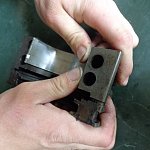
Here's a closer view and notice that the inner lips of the seal has a knife edge on it... This edge goes toward the front of the engine...
Here's a closer view of the knife edge....
Here I have highlighted it in red....
Put a nice bead of RTV in the block groove for the rear main seal like this...
Then use your finger to smooth it out evenly like this...
Next install the rear main seal making sure to press it all the way into the groove... Some of the RTV will squish out, use your finger to remove the excess....
Now put a bead of RTV in the rear main bearing cap like with the block...
Smooth it out with your finger...
Press the rear main seal into the rear main bearing cap...
Smooth out the excess RTV with your finger....
*************************************************************************
Install the bearings:
You must be diligent to keep everything extremely clean when installing bearings... I use painter's tack cloth to clean up any lint or debris from the bearing surfaces where the back of the bearings seat... You must keep any lint or debris from getting on the surface of the bearing and back surface where the bearings seat... I've seen a spec of dirt or piece of lint or thread from a cloth make the bearings tight, or even lock up a crank completely... You must strive for perfection and get these surfaces hospital clean...
Here's some different brands of tack cloth that you can get... I recommend picking up a half dozen or more to build the engine as they are cheap enough... You can buy tack cloth at any hardware or home improvement store...
Here's the tack cloth opened up...
Clean the bore where the back of the bearings go before installing the bearing shell...
Then clean the back side of the bearing before installing it in the cap...
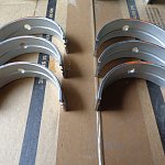
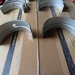
Here are the main bearings from the kit... Notice how most of them have holes in the center, except for the rear main bearing... Make sure that the ones with the holes go into the block to let the oil get into the main bearing holes that we probed in the last section (part 4)...
Here's the one without the hole... This one goes into the cap so it doesn't block the oil flow into the block...
Here's the other main bearings that have holes in both shells... These can go into the cap or the block... It doesn't matter if the cap bearings have the hole, but it's important to have the hole in the block side...
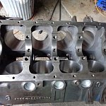
Here's the block showing the oil holes in the mains of the block...
Clean the main bearing bores with a tack cloth before installing the bearing shells...
Now put the main bearing shells in making sure that the ones for the block have the oil holes in them and the holes in the bearing line up with the ones in the block...
Line up the tab/anchor slot side first, then press the other side to seat the shell into it's seat.... Press on both sides to make sure that it's centered in the bore and both ends are even with the channel in the block bore...
The rear main shell in the block...
You may want to probe the block with the wire coat hanger to make sure that the holes are still open...
Now put the shells in the main bearing caps... The smaller shells go into the #1, #2, and #4 main caps... Wipe both the cap surface and back of the bearing shell with a tack cloth before mating them together....
The thrust bearing has more resistance to install as it has the flange on both sides... Line up the anchor slot side first, then press on the other side until you get it fully seated and both sides even with the bottom edge of the cap...
Note that on all of the caps except the rear main seal cap that there are numbers on one side and the letter "Z" on the other... The numbers should all be on the same side when they are all in the proper position...
Here the numbers are circled in red and the "Z" is circled in yellow....
Now wrap the tack cloth around each main bearing journal like this and go back and forth to clean any dirt and debris off of the main journals...
Repeat this for all 5 main bearing journals....
Here they all are circled in red....
Now carefully install the crank into the block... You want to install the crank dry right now as the plastic gauge needs to be done dry without any lube to alter the readings...
Now line up the anchor slots/tabs on the cap and block to be on the same side so they oppose each other and keep the bearing from spinning... The number one cap goes on the first main in the front of the block and then put them on sequentially in order... You cannot mix and match the positions of the caps as they have to be mated to the same main as they were originally machined on... If you mix the caps to a different location than they were machined, there could be a mis-match in the bore enough to make the crank tight...
Here the anchor slot is circled on both the block and cap... Install these so they are together for each main bearing cap...
Here's another view of them...
Now after all of the main bearing caps are in position, look at the markings on the cap and verify that the numbers are in sequence starting with #1 in front and increasing as you go toward the back and all the numbers are lined up on the same side....
If you aren't using new main bearing bolts and are re-using the old ones, run a die down the threads of the bolts to clean them up like tapping the holes... The dies usually are 1" hex and you can use a die wrench, 1" socket, or 1" combination wrench to run the die down the threads... Just run it to the bottom of the threads and don't try to make more threads as in most cases the shaft of the bolt may be larger than the outer diameter of the threads and you can break your die...
Here's a couple views of the die on the threads... This will clean up the threads on the bolt so they will be able to run down the threads in the block with minimal effort... Do this for each bolt...
Another view of the die on the bolt thread...
If you are using a windage tray, use the special taller bolts on the #2 and #4 main bearing caps... If you are not using a windage tray, then use the same style of bolts in each position....
*************************************************************************
Plastic Gauge:
Don't fully torque the bolts yet as now you need to plastic gauge the mains to make sure you have the proper clearance... I like to torque them to 50 ft * lbs (foot pounds) to keep them tight for the plastic gauge and torque the one that you are plastic gauging to full torque...
You don't want to keep torquing the bolts to full torque, as every time the bolt is torqued fully there is some permanent stretch in the bolt... You need to minimize how much you stretch the bolts as if they stretch too much they will start to 'neck' down and may weaken the bolt to where it can't make proper torque/clamp load on that joint... This is why I only torque them to 50 ft * lbs for the ones that I'm not gauging to keep from over stretching the bolt...
Here is the plastic gauge... There are many different ways to buy it, you can buy it in sets, or individually... For the mains and rods, you will want the green plastic gauge which measures from .001" to .003"...
Here's a tube that comes with three different size of plastic gauge...
Here's a Mopar Performance set that comes in a bag and has all three sizes also...
Here's some Sealed Power plastic gauges that come separately... This is the most economical way to buy them as you only get the one that you need...
Here's all three types shown together....
Here's a close up of the Sealed Power green plastic gauge...
Here's a view of a strip of plastic gauge with a light behind it where you can see the thin strip of plastic gauge inside of the paper...
Cut the paper into small strips here with the full scale for each one...
Now open up each one as you use it and take the small thin strip of plastic gauge out and place it across the main journal across the radius, not in the same direction around the curve... The plastic gauge should remain flat across the journal... It will sometimes try to stick to your fingers, so be careful to take it out and place it carefully across the journal...
Now put that cap on the journal and torque it to 85 ft * lbs as called out in the back of the engine chapter 9 in the service manual torque specification chart... Then remove that cap after torquing it being careful not to move the crank which can squish the plastic gauge more and give a false reading... After getting the cap off, you will see the plastic gauge may have a spot where the groove in the bearing is and it didn't get smashed... Measure the part that is squished with the scale on the paper for the gauge...
It helps to use needle nosed pliers to hold the paper scale up to the plastic gauge...
Here you can see that the clearance is .0015" which is within the .0005" - .0015" desired spec from the back of the engine chapter 9 of the service manual... Maximum allowable clearance is .0025".... The wider the plastic gauge is crushed, the tighter the clearance... A narrower squish has more clearance as it is not compressed as much...
If you can't read the plastic gauge on the crank journal, you may be able to see it better on the cap side of the bearing to measure as seen here... You may want to record each reading in a log book to keep for your records...
Now clean the plastic gauge off the main journal and the bearing of the cap with parts cleaner and put them back together dry... Use a tack cloth to keep it clean before reassembling if necessary....
Repeat this for every main bearing... Torque each cap to 50 ft *lbs for now to keep the crank tight while measuring the other mains...
*************************************************************************
Install the crank:
Now remove the crank after checking all of the mains and lube the bearings... You can use STP or Casite Motor Honey to lube the crank journals....
Here's the STP...
My first choice is the Casite Motor Honey...
Now pour the Motor Honey on each bearing making sure to cover the whole bearing to lube it good... This will keep it lubed while building the engine until you start it and the oil pressure will then take over...
Before installing the rear main bearing cap, put a dab of RTV on each end of the seal that butts together to help seal any gap that may be between the two halves... You can put the dab on either the block side or cap side of the rear main seal...
If the journals get any dirt on them clean it off with the tack cloth before putting the crank back in... Then install the crank carefully setting it in place... Install the bolts and snug with a 3/8" ratchet to run them down all the way...
I like to tighten higher torque in stages... The service manual calls out 85 ft * lbs for the main bearing caps, so I like to pre-torque them to 50 or 60 ft *lbs first, then go back and torque them to the full 85 ft * lbs...
When using a torque wrench, pull slowly and evenly and to not jerk or 'snap' the torque wrench as this may cause it to 'click' prematurely and not reach full torque... Pull with slow even pressure until the wrench clicks... Or you may use a beam style torque wrench and also use slow steady pressure when torquing... I like the convenience of the 'clicker' torque wrenches...
If you use a clicker torque wrench, make sure to back it off when done so it doesn't loose accuracy by not releasing the pressure of the spring that is used to set the torque... Springs may relax under pressure over a long period of time which may cause the wrench to loose some of its accuracy... This will help keep the clicker torque wrench more accurate over time...
Now after all of the main bearing caps are torqued, try to rotate the crank by hand... It should turn with some moderate resistance by using one of the counter weights to spin it by hand...
If the crank is too tight, loosen each bearing one at a time and try to rotate the crank... Keep loosening one at a time until it becomes easier to turn and then check the one that made the most difference... Remove that cap and check the bearing surface that contacts the crank journal and back side for any dirt or contamination and clean it off and reassemble... Like I have stated before I've seen a small speck of dirt or piece of fuzz or string from a shop towel or cotton glove get on or behind a bearing and make it tight, even to the point where you can't rotate the crank...
However if you installed the crank properly and kept everything clean with the proper clearances, it should be fine and turn by hand with some resistance... That is why you plastic gauge and verify the clearances are correct...
*************************************************************************
Now that the crank is installed with the proper clearances and it rotates properly, you are ready to install the pistons...
You are now ready to move onto section 6 - installing the pistons...
*************************************************************************