At home flywheel balance....

-
So you couldn't come up with a sound engineering explanation, so now your resorting to some sort of George Bush style scare tactics?
LOL, Chrysler spot welds hunks of metal on external balance converters and even sells a kit for the DIY guy to use and that doesn't seem to bother you.. Come on dude , get a grip.

What exact explanation are you looking for?
 
What exact explanation are you looking for?

Is that question in relation to what you quoted? Because it's doesn't really make any sense. Kit was the one who needed to provide the explanation to back up what he was saying..
 
I have no idea how "you" will attach the weight(s). All I suggested was the concern safety of others. Welding is a subjective term.

I can only recommend you source the correct flywheel for the application.
 
I wish you the best of luck.

I do a bunch of R&D, and enjoy the work, and learning. I hope to make my own digital tire balance machine. For now I use an old Hunter on the car. As others suggest, the low speed of a tire, balance is much less critical than on a flywheel.
 

Attachments

  • 20150520_115307.jpg
    84.7 KB · Views: 275
Really, #-o why would you say that??
Tell me.. just what am I doing that could cause the flywheel to explode.??

It is what it is. It "is" a object that has the potential to reach 8,000 rpm on a missed shift. It can, will and has killed and maimed people. If your experiment fails and it vibrates like hell I hope you get it shut off before it kills your dumb *** or someone else. I am sorry I got no tolerance for morons. You want to experiment do it with something less violent. You ever seen a flywheel explode ????? If you had you would not be playing games with it. Do what you want but it is a 40-50 year old piece of cast steel that has been spinning around behind a motor for god know how long. It has stress cracks galore. Gee Wally I got a idea lets change the balance on this and see what happens. You were warned
 
It is what it is. It "is" a object that has the potential to reach 8,000 rpm on a missed shift. It can, will and has killed and maimed people. If your experiment fails and it vibrates like hell I hope you get it shut off before it kills your dumb *** or someone else. I am sorry I got no tolerance for morons. You want to experiment do it with something less violent. You ever seen a flywheel explode ????? If you had you would not be playing games with it. Do what you want but it is a 40-50 year old piece of cast steel that has been spinning around behind a motor for god know how long. It has stress cracks galore. Gee Wally I got a idea lets change the balance on this and see what happens. You were warned

I'm not doing any modification to this flywheel that a regular machine shop wouldn't do.
Drilling the wheel.. Yep regular machine shops do that as well as Chrysler itself.
Adding weight, yep regular machine shops do that as well genius .
Static balancing, it's a tried and proved balancing method.
Mc Leod. 440 source and a bunch of other manufactures have bolt on weights as well.
How would you know if the flywheel has stress cracks? Have you seen it? No, you haven't , have you? It's a perfectly serviceable unit.
From your reasoning, everyone who uses a 40 -50 year old factory flywheel is in danger. It's like being worried about your 40-50 year old crank... #-o
Again, your another one who missed the part where I said the wheel would be checked on an electronic balancer at the end of the experiment.
I think we have established who the true moron is here. If your going to run your mouth, at least understand what your talking about and pay attention to previous posts.
Just another naysayer #-o
 
"Have a look how they balance V twin motorcycle cranks"

lol, I spent 2 years in a Harley shop.

Hey Kit,
I spent nearly 6 years in a Tire Shop doing alignments,and never saw one of those there. I remember seeing them tho in the 60s and 70s
 
25 years ago I had drilled a flywheel at home myself to use behind a cast crank 440.
I didn't even use the correct recommended drill size from the Mopar bible.
Just calculated the space that was to be removed with the intended bit and converted the
volume to get the depth of the closest sized bit I had on hand. Even had a different degree cutting edge. Size and depth of holes were not to the print when done but the placement and volume of metal removed was. Used my drill press. Couldnt have done it without mopars instructions and a machinist hand book.
Worked great with no vibrations for years and still have it. Got plans to use it again on a different cast crank 440 engine soon. I drove it very hard without incident.
We are lucky that ma mopar makes this kind of info available. The handbook and a calculator is really usefull also for those of us that are mathematically challenged.
It really wasnt that scary then and I would do it again without any fear now that I have proven to myself the Mopar prints are sound.
Never welded to a flywheel before so I got nothing for ya there cept steel generally welds easy.
 
Nakerlite,

I commend your desire to experiment, especially with the comment that following your results will be a :pROPER: check on an electronic / digital machine, I wish you success.

That said, I personally would recommend a different fixture than the roller bearing you have. I'm an A&P (aircraft mech) by trade and profession. During the pre-digital age, aircraft propellors were balanced by inserting a tight fitting shaft through the bore of the prop, and then the ends of that shaft are placed on parrallel, horizontal knife edges for minimum rolling resistance.

Sometimes items were attached or adhered to the individual blades, or sometimes material may have been removed. This method was accurate enough iin obtaining static balance that it had to happen in a closed shop so as to be a "No Wind Environment".

That's my food for thought.

Mike in FL
Mike, yes I have seen the fixture you are talking about and I was going to use that type, but decided to try the bearing first. I may still build that type to see what differences there are in the rolling resistance and how many grams it takes to move the wheel to BDC.
 
25 years ago I had drilled a flywheel at home myself to use behind a cast crank 440.
I didn't even use the correct recommended drill size from the Mopar bible.
Just calculated the space that was to be removed with the intended bit and converted the
volume to get the depth of the closest sized bit I had on hand. Even had a different degree cutting edge. Size and depth of holes were not to the print when done but the placement and volume of metal removed was. Used my drill press. Couldnt have done it without mopars instructions and a machinist hand book.
Worked great with no vibrations for years and still have it. Got plans to use it again on a different cast crank 440 engine soon. I drove it very hard without incident.
We are lucky that ma mopar makes this kind of info available. The handbook and a calculator is really usefull also for those of us that are mathematically challenged.
It really wasnt that scary then and I would do it again without any fear now that I have proven to myself the Mopar prints are sound.
Never welded to a flywheel before so I got nothing for ya there cept steel generally welds easy.
You just have to have faith in your abilities, don't you :)
Yes, it would be good to have a different diagram available with a more common user friendly drill bit and location than what Mopar has ;) I read of members here taking their flywheels to machine shops just to be told they need to get a drill bit first before they can do the job.
Just to clarify, I won't be welding any weights to the wheel, I will be bolting one on , just like McLeod etc do. If I get really interested, I might design a balance plate specific to the 360 like they do for SB Chevs. Quicktime have them but they are not SB 360 specific.
 
Having been thru having a flywheel that was surfaced with a small piece of grit between it and the machine cause a vibration only in a narrow RPM range I'm wondering how you're going to verify that you got imbalance in the correct angular location? Or am I misunderstanding the goal?

When a balance shop neutral balances a flexplate o a flywheel they fit is to a mandrel that then sits in a cradle at each end made of two bearing each - 4 bearings total. Those cradles are attached to the transducers, but what's important to you is that thru the ratio of bearing OD to mandrel shaft OD those bearings aren't turning very fast compared to the mandrel's RPM.

When a balance shop "match balances" one flywheel to another they are mated 180° out of phase and back to back. Then the new flywheel is machined or drilled to a "neutral" condition for the pair of flywheels.

If an iron flywheel hasn't ever been spun up very fast it probably doesn't have any cracks. If it has been spun up then it does. How fast is "up" depends on the unit itself. Absence of being able to see them doesn't mean they're not there. Doesn't mean that they are there either, but which is the safer perspective to take?

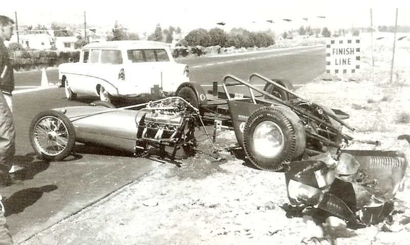
Extreme example of what a flywheel explosion can do:

scan0100-1.jpg
 
If you were talking about a steel flywheel then very little of this would apply. Since you're talking about an iron flywheel, and given their demonstrated potential for disaster you would do well to set your bravado aside and give them the respect that they require. Iron is subject to brittle failures when loaded this highly. The results are well documented. A laise faire attitude isn't going change anything except potentially your nick-name.

I'm not saying don't do it. I'm saying be aware of the potential for disaster and be cautious about what you do and how that might effect the outcome.

Auto's are no less immune from such a catastrophic explosion.

OTOH, most of your posts seem to be more about poking the bear and less about the actual act of doing what your proposing, so perhaps you've no intention to do any of it and you're only trying to ruffle some feathers. In which case I'm done here.
 
I'm not sure why you would think that I have not evaluated the potential hazards of this project.
I'm also not sure why people are freaking about making changes to a flywheel that are commonplace, maybe it's because all people seem to know about flywheels is that they can explode, so that's all the can focus on.
I'm going to post the results when the work is fully completed. It's going to take a little longer than a Saturday afternoon to complete, then there is also the workshop time and expense that will be coming out of my pocket so others can see the results.
 
What's the status on the project?

To address what someone posted earlier: Chrysler uses those huge drill bits because larger radii reduce the potential for stress and fatigue fractures. I'm not saying that I would insist on those sizes, the metal removed and where it's located is all that matters. That's just their reasoning.
 
You just have to have faith in your abilities, don't you :)
Yes, it would be good to have a different diagram available with a more common user friendly drill bit and location than what Mopar has ;) I read of members here taking their flywheels to machine shops just to be told they need to get a drill bit first before they can do the job.
Just to clarify, I won't be welding any weights to the wheel, I will be bolting one on , just like McLeod etc do. If I get really interested, I might design a balance plate specific to the 360 like they do for SB Chevs. Quicktime have them but they are not SB 360 specific.

I like the fact you are thinking this out, instead of commitment to a machine shop. Kudos, & good luck.
 
What's the status on the project?

To address what someone posted earlier: Chrysler uses those huge drill bits because larger radii reduce the potential for stress and fatigue fractures. I'm not saying that I would insist on those sizes, the metal removed and where it's located is all that matters. That's just their reasoning.

Should be doing it next week.
 
Well let me tell you that YES it can be done! How do I know ? I did it and ran the flywheel for 4 years. Ma mopar put out the specs when the 360 first came out showing where to drill , what size drill and how much to remove.

I will see if I can find the paper work. I needed a flywheel for my 4 speed that would fit my scattersheild and all that were available were 11" from a truck (which won't fit my 10.5 " scattersheild).
 
It's all good, that Mopar tech on the weight is available all over the net.
 
Have a look how they balance V twin motorcycle cranks ;)
The use of clay looks similar, the static methodology is not......maybe you have some other examples on that......

[ame="https://www.youtube.com/watch?v=Jn50F_yKW0s"]Harley Crankshaft Balancing - YouTube[/ame]

Not sure how you will know if your method is in any way accurate or if you get lucky and hit the balance right on these 1-2 tries? I.e., could it be repeated in the field by anyone? The source of error will be the bearing stiction that has been referred to and is a very real issue. (And which is something I have actually done and have seen the criticality of having essentially 0 bearing stiction.)

The example of the old prop balance method addressed that very issue; but that worked adequately because the prop RPM's are limited to about 2800 rpm, AND perhaps more critically, the moments around the center are huge compared to the case of a flywheel (the props typically will be 55" or longer), so small imbalances generated a lot of relative imbalance that could be found with reasonable accuracy and repeatability, and with the small bearing friction of the knife edges.

You'd have better prospects with a fluid or air bearing.
 
-
Back
Top