Electronic ignition upgrade / voltage regulator question

-

challyrtse

Member
Joined
May 8, 2009
Messages
21
Reaction score
0
Location
Richland, WA
I upgraded to an electronic ignition setup when replacing my engine years ago. No problems there, but recently I had read that if you do this it is essential to upgrade to a "new style" voltage regulator and start using a two-field alternator.
I did not do this back then, and have run the car for years since. Is this really necessary? I would hate to be slowly damaging the system due to my own lack of knowledge...
Also, if you do upgrade to the newer voltage regulator, how detailed of a swap is that?
 
I have never heard of that being the case but my only guess is the late model regulator and two field alternator is going to give you more amps than the early model regulator with one wire alternator. This will help the electronic ignition run at optimum performance.
 
The big problem was that the old style voltage regulator was just an on/off switch. These little spikes propagated through the electrical system and could fry the ECU of the electronic ignition. There are electronic versions of the old style mechanical regulators avaialable that look like the mechanical but regulate like the newer electronic. the difference in placement of teh regulator in the circuit is why the newer requires two wires. Old style -hot to regulator to alternator to ground; new - hot to alternator to regulator to ground
 
There was another concern with the old style regulator. It would have the alternator charge at 13-13.5 volts with the old point ignition, where as with the high voltage ignition the system would supposedly want 14.5 volts which is what the newer regulators were set for.

Terry
 
Its very simple to change over to a dual field alt and late (electronic) voltage regulator.
 
Great! Thanks for all of the replies, guys.
I had stored my car for about 6 years, and recently got her back running. When I did, the ECU fried and had to be replaced. I wonder if those voltage fluctuations from my old regulator did that slowly over time?
I've been meaning to replace my alternator anyway, might as well change the whole system while I'm at it.
What year did they start using the newer system? If I went to the parts store and told them to get an alternator and regulator from a 1970 318 Dart, do you think that would work?
 
could the old style voltage regulator prematurely pop ballast resistors? I seem to recall a friend of mine having that problem every month or so. really frustrating. he always had a spare in the glove box though.
 
Its very simple to change over to a dual field alt and late (electronic) voltage regulator.
Someone has went to the solid state regulator and 2 field wire system on our 67 dart with 70 318 eng. Is this OK to run with old style single points system? What year are the solid state regulators from incase I need a new one?
 
Yes, I have heard about that when I bought my Mopar electronic ignition system. I never changed over though. I probably will in the near future. As far as burning out ballast resistors, I say no way......probably a shorted out coil IMO.
 
just get a replacement regulator that is electronic, no need to change the alternator.
 
Where can you get electronic replacement regulators?
A regular parts store, through Summit or Jegs, or is there a place to special order them from?
 
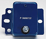
I always used a P3690732 regulator on my pre-72 cars that were retro-fitted with electronic ignitions. As someone mentioned the old style regulator was an on/off style and the newer version was always on. I think you can just do the regulator and you`ll be fine.
 
Year One has an electronic voltage regulation for 1961-1969 which looks like the old mechanical one. $36.00. Don't know if that's what tedsweet was talking about.
Maybe someone else has tried one of these,and will let us know how they work.
 
Where can you get electronic replacement regulators?
A regular parts store, through Summit or Jegs, or is there a place to special order them from?

I recommend upgrading to the later model charging system. I did that to my 67 cuda.... one wire solid state to two wire electronic regulator with 75 amps. Also did madelectrical.com amp gauge bypass. I installed a voltage meter later on. Ran a 4ga wire from the alternator to the starter solenoid. My headlights was brighter is one thing that I was after and they don't dim at red lights any longer. You can get everything you need at the local parts houses.
 
I've been using one of these since changing over to electronic ignition on my '66 Cuda.

312-P3690732.gif


Found this link for Jegs. http://www.jegs.com/i/Mopar+Performance/312/P3690732/10002/-1

Haven't had any problems running the stock alternator. Don't know why it says for race only, seems to work just fine. Would be nice to have more amps though, will probably go with a later model set-up when I finally get around to rewiring the car
 
Seems to be a little mis-information on this thread.

Whether you have an early system with a mechanical regulator or a latter system with the solid state regulator they both just act as a switch to turn power on and off to the field windings. In either case they are designed to keep the battery voltage in the 13.8 to 14.1 volt range. Approximately 1-1.5 volt over the nominal 12.8 volts of the battery is necessary for current to flow into the battery and charge it.

The only explanation I have heard for the need of an electronic regulator that passes the common sense test is that the mechanical regulator creates more noise in the electrical system than a solid state regulator. The thought was this noise could interfere with the operation of the electronic ignition module.

The stock replacement regulator for pre 69 charging systems from Wells that is available at most chain parts stores is a solid state replacement for the old mechanical regulator. Its easily identified by the case being only 1/2" thick.

The MP regulators that are advertised as constant voltage regulators do not work any differently than the parts store regulators. They maintain the battery voltage in the 13.8-14.1 range.
 
i would goto the dual fld set up. just seems to be a lot more stable to me. i know guys that have used the blue constant out put regulator but i never trusted those things.


here is the conversion diagram. you add the wire i have colored blue..

new0regulator2.jpg
 
i would goto the dual fld set up. just seems to be a lot more stable to me. i know guys that have used the blue constant out put regulator but i never trusted those things.


here is the conversion diagram. you add the wire i have colored blue..

new0regulator2.jpg
This is a good diagram of the charge system, and I don't want to hi jack this thread, but can you tell me where the ignition 2 wire goes off the ballast resister. This might benifit challyrtse also. And does it matter if the field wires are hooked up opposite? Thanks.
 
The ignition 2 wire goes to the ignition switch. When the key is in the start position there is no power on ING 1 and power is applied to ING 2 to bypass the ballast resistor while cranking.

And, it does not make any different which wire is attached to which field terminal.
 
Thankyou very much Dave. You guys are great. The only reason I asked is because I am STILL having charging problems. I had my alternator rebuilt, purchased a new regulator, mounted all and made sure grounds were very good, started her up and guess what, 17.5v! And get this. I had her charging great at 14.8v before I done all this. So I made temporary wiring and bypassed all original wires, still the same. The only thing it pointed to was the new regualtor was bad. Put my old reg back on, 14.8v. Reinstalled the new reg, 17.5v. Put old reg on again, 14.8v. Took the new reg back to the alternator rebuilder, they tested it and sure enough it was bad. They replaced it with another new one. Scared to death to try this new one. If this gives me trouble, what the f$*^ am I supposed to do ? Talk about sh&* house luck!! Sorry for the rant. I want to trace all wires, so this is why I asked where the Ign 2 wire went. Thanks again, really appreciated, Keith.
 
This thread hasnt been active for a few weeks so I dont feel as bad about hijacking it briefly.

I found my Summit CD ignition system was not putting power to my plugs when the starter was engaged. Based upon the diagram and discussion in this thread, Ignition #2 would seem to solve my problem. I am just having a problem identifying which wire it might be. Could someone take a look at the picture and point it out to me? I was previously connected to the wire with the tape on it.

In the alternative, I dont seem to need a ballast resistor any longer. Would I be better off just removing it and connecting all the wires together? Possible coil damage would seem to be the only reason not to. I am running a Pertronix Flamethrower I coil if that matters. Thanks.

Ballast Resistor2.jpg
 
-
Back
Top