fstfish66
Well-Known Member
trans tunnel looks great,,,i also was going to put a gauge in the ask trey,,but never did,, that dah in that car will really look custom,,,comming along nicely,,
This is where I get some of my ideas and parts from, my transmission and rearend have 4,000 miles on them that is new to me. When I am not building aerospace parts I live and work here small apartment above the main shop area
nice job man,, yes you should start your own topic on this build,,,
a back yard of parts,,,cant beat that,,
Broke ground on my new shop, it will only be 2,000sq ft but the price is right we should be pouring concrete on sat will post pics
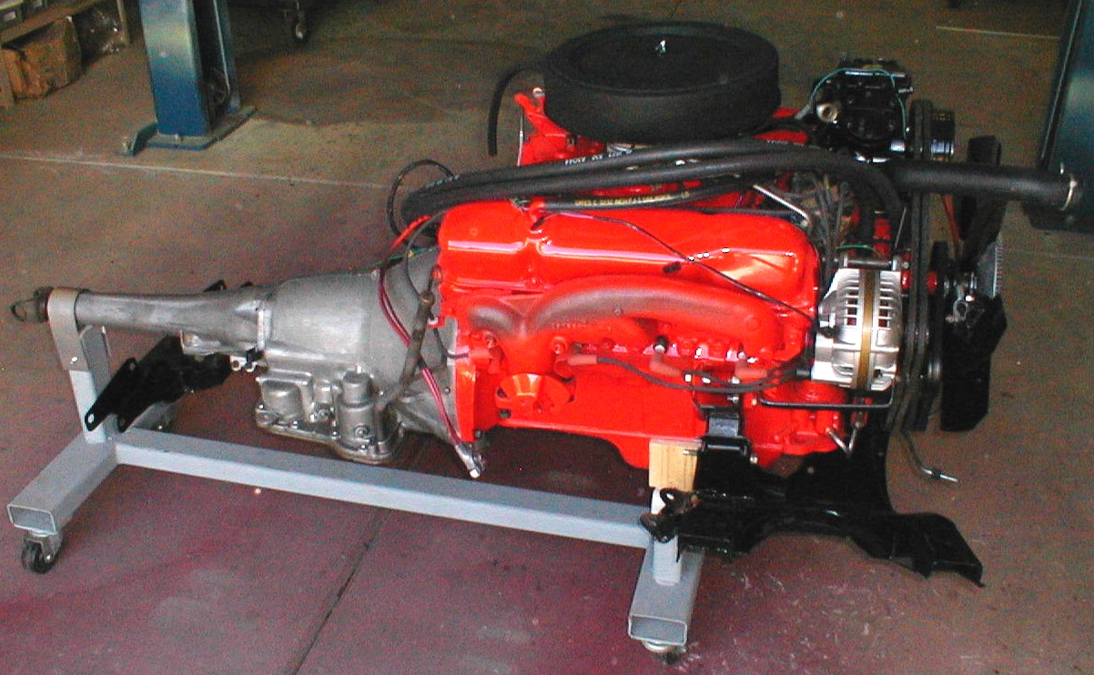
I would caution against using the cherry picker. It is designed to have the load point inside of its perimeter (not to mention the picker will be in the way). Instead, make a set of plates that will mount to the frame at the bumber mounts. To them, mount (weld) 4x6 box metal beams to make a a stand that is the distance to the floor plus enough to weld plate on). It should have holes bored through at 2 inch intevals. Use 3x5 box metal beams inside of these so that as you jack up the car, these will drop down. Use a 6 inch bolt to push through the 4x6 to set your level. Being bolted to the car makes this very stable. Further, if you weld heavy metal casters, you can move the car. Additionally, if you make a set for the rear, you can get your car up off the ground to do all around brake work or tire rotation and is great for working under the car. Installing the front end assebly described above is a breeze! You can adjust the dimensions to suit your needs. My buddy made these for his 69 cuda vert when it went to the body shop, and they have been on the car since. We are about to put just such an assembly on next month.Check this out. I did a little searching on my own as well. Very cool Road Runner with a 383. Looks like a full concours job almost.

Here is the site where I found it. Wish I could find plans for the jig used. But I'm sure it is not too hard to design.
http://www.hoffmanswinnerscircle.com/69rtconvertible/Engine_Related_Photos.htm
It's just a matter of building the engine/trany/suspension dolly and getting the car hoisted up in the air enough. I'm thinking I will bolt something to the front bumper as an attachment point for my cherry picker. I wonder how high I can get it.
Tapped in the roller pilot bearing and did the RUNOUT inspection on the bellhousing. I've never used a dial indicator before but it was not too hard to figure out. I have a couple of tips on this process. I did not install the pressure plate and clutch disc onto the flywheel. This would provide an uneven attachment surface for a magnetic dial indicator. I found that removing one flywheel bolt made it easier to attach my magnetic dial indicator. I checked the RUNOUT 5-6 times at different positions just because I'm nerotic and I didn't want to make a mistake and void the warranty. The MAX RUNOUT is 0.005". The total RUNOUT on my bellhousing was about 0.013" which means I would need the 0.007 offset dowel pin set. Here are a couple of pictures. I'm stalled on the conversion until I get the dowel pins from Keisler. Once I recheck the RUNOUT with the offset dowel pins I'll put everything together and have it ready for the suspension/engine/tranny cradle.
Roller Bearing

Dial Indicator setup

Inside the Bellhousing

-Dave :headbang:
