Low volts at idle

-

dartkory

Well-Known Member
Joined
Nov 22, 2007
Messages
301
Reaction score
3
Location
Portland Oregon
So I have been reading up on many post so to save confusing myself I figured I'd start a new thread. My problem is that my volts drop to about 12 when I'm in drive at idle but instantly jump when I give it gas. With my headlights on the volts drop to 9-10 and my electric gauges start bouncing. I'm gonna be doing the relays for my headlights that I've seen in other posts but that won't help the low volts during the day. Does anyone know the fix for this? I was going to buy the powermaster alternator but apparently that won't help at idle. Thanks for any input! -kory oh and I have already checked and replaced my alternator and regulator and replaced the wires that go to the alternator but with no change
 
I have already checked and replaced my alternator and regulator and replaced the wires that go to the alternator but with no change

I don't know what this means?

Are you still using the old style "roundback" alternator?

http://www.forabodiesonly.com/mopar/showthread.php?t=187013

Have you read the MAD electrical article?

http://www.madelectrical.com/electricaltech/amp-gauges.shtml

You say "Replaced the wires" which means exactly what?

Many guys have gotten away from the original old style round-back design. Even simply going to the 70's later "squareback" design is some help. If you do some searching, there's lots and lots of posts about conversions to other designs, including Delco integral, Denso, Ford, you name it.

This is all in the alternator design, which was improved some in the squareback. If you still have the 69/ earlier type system, you can easily use a squareback simply by grounding one field terminal. The older design alternator simply is unable to output as much at very low RPM.

You may have multiple problems. Voltage drop in various harness connectors, including the bulkhead connector, may be adversely affecting your voltage in the car at low RPM

The other thing is, "what is your load?" and "what is your idle speed?"

If you have halogen/ etc upgraded lights, or other accessories, this can certainly load the system, and if the idle speed (stock /6, etc) is too low, that is a factor.
 
Sounds like you have excessive voltage drops in the wiring. The battery alone should supply ~12 V to the cabin if it is OK and charged. The alternator is just to recharge the battery over the long-term. Step 1 is clean the battery terminals and insure the cables aren't corroded there. Step 2 is to find the voltage drop in the system, using a multimeter. Likely culprit is the bulkhead connector. The terminals in it can be removed and cleaned. The connectors at the ammeter on the back of the dash can get corroded, and get so hot as to melt things. All current from the battery to the cabin goes thru the ammeter.
 
Have you load tested the battery? 12-13v at idle with an old 1 wire alternator is fine. Dropping to 9 or 10 with the headlights on is not good but that could be from a bad battery.
 
I could have sworn that last time I had my dash apart the ammeter wasn't even hooked up! I'll have to check that out again. I'm running the square back design right now and my idle speed is around 800 rpm. The wires that connect to the alternator are the ones I replaced. And only upgrades as far as electrical is a CD player and a few gauges. I'll check out that artical and hopefully find some pointers. Thanks for the help! -kory
 
The really big problem is usually the bulkhead connector

Where are you measuring the "9 volts?" And are you sure the meter is actually accurate?

This stuff is really easy to check out. One thing to keep in mind is that (if you still have a factory harness) that the main junction for major power feed is the factory "in harness splice" which is in the black ammeter wire in the under--dash harness, a few inches away from the ammeter. These can and HAVE failed.

Probably the best places to check voltage which are fairly easy to access is:

The black/ red wire feeds into the front and out the interior of the bulkhead connector

If the ammeter is disconnected, they must be spliced together, and the original molded connectors could be suspect. That's a high current splice and must be a good connection

Check at the main feed into the fusebox. If that is low, but the bulkhead test point looks OK, then the "in harness splice" or ammeter connections are suspect.

Make these checks with engine off, and a load such as heater blower/ headlights on. To avoid ignition problems, you can pull one end of the ballast resistor loose so that leaving the key in "run" won't hurt anything in the ignition.

To get very deep into this, we need details about what exactly you did. That is, have you changed the wiring, how did you unhook the ammeter, etc?
 
I read that mad artical and so I'll be checking the volts the way you explained but considering my bulk head connector looked the same as in that artical (melted where the main power wire is) I'm going to drill through it the way they explained and bypass the ammeter. For some reason I remember the connections that go to the ammeter loose and when I went to tighten them to the posts on the ammeter they made a big spark. It seemed like it would be a bad idea for those to touch but if they are ok to put together then that's what I'll do
 
Both red and black on the ALT gauge are hot through the gauge. A sprk means your tool touched a ground source, i.e. short to ground. That could have killed the voltage regulator or diodes in the alternater.
Always diconnect the neg' battery cable when working with electrical.
 
If the car is street driven only I have fixed this problem by just swapping to a smaller alt pulley ! The factory used about a half dozen different diameters thru the years.
 
It seemed like it would be a bad idea for those to touch

An ammeter is a series instrument just like a piece of wire. They already "touch" electrically. You have to understand what MAD is advocating there. Their method is sort of a "cheap fix." They are essentially modifying the system so that the black and red wire become a parallel circuit so that both act as a power feed into the car. The jumper added from the alternator to the battery connects the "engine end" of the red/ black together, just as jumpering the ammeter end does. Connecting the ammeter ends together and eliminating the ammeter, simply insures that the ammeter is not going to become part of a problem, and if it's been damaged like the one in the article, it already "is" part of the problem.

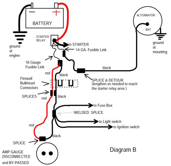
Look at the diagram from page two of the article:

http://www.madelectrical.com/electricaltech/amp-gauges2.shtml

You can follow from the ammeter where the black/ red have been connected, back through the bulkhead, and see that they have cut the old black wire and spliced it into the red. These two thus become "one wire" and that doubles the capacity of that feed.

Additionally, the black feed from the alternator is now DIVERTED directly back to the battery. This means that the alternator current no longer has to go clear through the bulkhead, through the ammeter, and back out on the red wire to the battery. We have eliminated several feet of wire, as well as two possible bad connections in the bulkhead connector.

THAT ALONE could be the cause of your low idle problem.

amp-ga27.jpg


It's important to point out that scads, thousands of these cars and trucks were driven for their useful lives with no problems. But even "back then" some of us DID have problems, and now that these girls are 40+ years old, time has caused more deterioration. Back in the days of my 70 RR, both the original owner and myself were radio amateurs. It melted the bulkhead connector during that time, and way WAY back then, I just drilled out the connector and ran new wires through for the ammeter connections.

It is VERY important to chase down voltage drop problems before you invest a bunch of money into alternators/ regulators. It might just be "all" of the problem.
 
I really appreciate the patience and help. It's just electrical has always been a little intimidating to me. So let me get this straight, after I bypass the ammeter and connect the black and red wire on the other end, does that plug into the same post as the battery on the relay? And does the alternator plug into that same post as well? And all the other wires on the relay untouched?
 
There are different ways to do this mod. Just re--read the article and follow through.

Or, you can do the engine bay a little different. Instead of re-routing the red/ black through the bulkhead as they did, you can run a NEW wire from the alternator output, over directly to the starter relay. Other than repairing or bypassing the bulkhead connector, and connecting the ammeter wires together, leave everything else connected as is.

Let's see. Look at the diagram. What you are doing is connecting both ends of the red and black together. This makes the red and the black one big wire, and because you are now going through the bulkhead on TWO connections doing the same job, you are reducing the current on each to 1/2 of what "the one" used to have to carry.

Because you have connected the alternator directly to the battery, the charging current no longer goes through the bulkhead. The only current the bulkhead connector now has to carry is the load current, like ignition, lights, heater, etc. It no long has to "see" the alternator as it's now hooked direct to the battery.

To put this another way, not only have you increased (doubled) the wire size feeding INTO the interior of the car, you have eliminated the charging current that used to go through EACH wire.
 
So you're saying to bypass the ammeter then just run a new wire from the alternator to the relay and leave everything else alone? Because right now I have 2 wires connected to the 1 post on my alternator and then 1 field wire. So if I run a new wire to the relay, do I have to remove either of the 2 that are currently connected to that same post?
 
The way I see that diagram and read the write-up, it looks as though you bypass the connectors in the bulkhead all together and drill through the connector to run wires directly though the plastic connector totally bypassing the male and females connections in the connector.
 
So you're saying to bypass the ammeter then just run a new wire from the alternator to the relay and leave everything else alone? Because right now I have 2 wires connected to the 1 post on my alternator and then 1 field wire. So if I run a new wire to the relay, do I have to remove either of the 2 that are currently connected to that same post?

Either follow the article exactly, or alternately, add the new wire. Leave the existing wire (s) on the alternator. I believe that one of them feeds your horn relay.
 
So after taking a better look at my relay, all that is connected to the big post is my alternator and starter and a thin purple wire. Then the screw below that has the other wire that goes to my starter then the 2 male slip fitting at the bottom have 1 wire going to each one but I don't know where they go. Do you know what the 2 connections at the bottom of the relay are for?
 
The two "push on" connections are one for the neutral safety switch, the other is the "start" signal coming from the ignition switch. Electrically, it does not matter which is which.
 
Do you know what that small purple wire might be?
Unlikely anybody could answer this unless you tell us the year and model of your car (maybe 66 Dart?), since wire colors changed year-year. A photo of your starter relay would help us help you.
 
-
Back
Top