Bypassing ballast resistor

-

fnaramore

POWEEERRRRRR
Joined
May 30, 2013
Messages
331
Reaction score
11
Location
Fairfax, VA
Replacing my ignition with a blaster 2 coil and msd ready to run pro billet distributor in my 73 dart with electronic ignition. Directions say to bypass the ballast resistor. It is a four prong ballast with two wires and a loop from the top to bottom on the left side and two wires on the right side. Can i just cut all the wires off and splice them like so?
wire one----/------wire three

loop l

wire two----/----- wire four

or is there a better way to do it?

Edit: it doesn't show up right in my little diagram, but I would splice the top of the loop to wire one and bottom to wire two.
 
Top / bottom doesn't mean much because I don't know how the thing is mounted.

Basically you have two resistors in one box. "The end with the loop" is the ignition feed and feeds power to both resistors. One goes to the coil, the other goes to the ECU. Use your ohmeter or follow the wire from ECU back to the resistor, and you can just eliminate "that side"

In the drawing below, what you can eliminate is on the left side. The "remaining wires" all get spliced together. What is NOT shown here is the coil bypass wire which goes from the bulkhead to the coil+ side of the resistor. "Colors vary" over the years, traditionally brown

Ignition_System_5pin.jpg
 
is another option just taking off both plugs and then feeding a metal connector to attach both plugs together? Sorry for the poor information. When I say top to bottom here is what I mean

img_5281-jpg.jpg


View attachment IMG_5281.jpg
 
Last edited by a moderator:
Yes, you can do that. Make sure the original connectors are in good shape
 
I'll be honest, I don't know much when it comes to the electrics side of cars. So since I am using a pro billet ready to run distributor, do I not really need the ecu to be part of the system? if thats true, I only need to splice to the two opposite wires on the ballast that don't connect directly to the ecu?
 
Okay, I think I got it now. So for this distributor and coil change, I only need to splice the wires on the ballast that connect to the positive side of the coil and the ignition. Can the other two wires just be left unhooked or should they stay connected to the ballast?
 
I'll be honest, I don't know much when it comes to the electrics side of cars. So since I am using a pro billet ready to run distributor, do I not really need the ecu to be part of the system? if thats true, I only need to splice to the two opposite wires on the ballast that don't connect directly to the ecu?

Are you using this product?
http://www.msdignition.com/Products...rysler_318-360,_Ready_to_Run_Distributor.aspx
It has a built in module. You do not use the original Chrysler module.

Okay, I think I got it now. So for this distributor and coil change, I only need to splice the wires on the ballast that connect to the positive side of the coil and the ignition. Can the other two wires just be left unhooked or should they stay connected to the ballast?
The only wire that is of any use to you is the brown wire with the loop to 2 terminals at the ballast resistor connector. No need to cut and splice anything else. Remove the Chrysler ignition module and ballast resistor. Ignore all the original wires, (except the brown wire at the ballast resistor connector), including the original coil wiring. Use the brown wire for your ignition feed and hook up as per the MSD directions.
 
yep, thats the distributor I'm using. I don't have a brown wire with a loop though. None of my wires are the same color. But I think I get it now, I need to attach the power wire to the positive coil wire and the rest are unused and can be removed along with the ignition ecu.
 
yep, thats the distributor I'm using. I don't have a brown wire with a loop though. None of my wires are the same color. But I think I get it now, I need to attach the power wire to the positive coil wire and the rest are unused and can be removed along with the ignition ecu.

Two of your ballast wires are powered (one in the start position and one in the run position)
Connect them together and power your new distributor off that, or it will only run in one or the other (start or run)

Using a test light it is easy to determine.
Unplug all the wires from the ballast.
Turn your ignition on and test the wires till you find a powered wire (that is the run position wire)
connect your tester to the other wire and turn the key to the crank position.
When you get a light in the crank position, you found the "Start" wire.
Connect those two together and power your new coil with it.

This how my HEI kits hook up also, so I know it works this way.
My car is a 73 also, and had the exact setup yours has until I installed the HEI.
I cut those two wires all the way back to the harness, connected them together and ran a new wire from the harness to the new coil.
Then cut all the original coil wire out.

Same with the factory module wires (I cut the wires off right at the factory harness and taped it all back up)

Hope this helps
 
Okay, getting closer to understanding haha So I traced one wire back to the positive side of the coil (brown wire). So what I need to do is find the run power wire and start power wire and then splice all three of these together. After I do this, I can remove the rest of the wires to the ballast resister and remove the ignition ecu itself.
 
Okay, getting closer to understanding haha So I traced one wire back to the positive side of the coil (brown wire). So what I need to do is find the run power wire and start power wire and then splice all three of these together. After I do this, I can remove the rest of the wires to the ballast resister and remove the ignition ecu itself.

Yep, that's is about it.
That way your current wire to the coil will have full 12 volts in the start and run position both.
 
Okay sweet! thanks for the help! So in this case, the only wires on the coil should be this power wire (in a threeway splice with the run and start power wires) and the positive and negative wire from the distributor. (the original negative coil wire can be discarded) Last question then is should I keep the condenser connected to the coil or should that be discarded?
 
The only wire that is of any use to you is the brown wire with the loop to 2 terminals at the ballast resistor connector. No need to cut and splice anything else. Remove the Chrysler ignition module and ballast resistor. Ignore all the original wires, (except the brown wire at the ballast resistor connector), including the original coil wiring. Use the brown wire for your ignition feed and hook up as per the MSD directions.

Uh,......................NO.....................not correct

You also need to splice the coil resistor bypass wire in which was the coil + side of the ballast
 
Uh,......................NO.....................not correct

You also need to splice the coil resistor bypass wire in which was the coil + side of the ballast

Wait, so am I right and just he is wrong or am I also wrong?
 
What you have..............

On the end of the resistor which is looped, you have power coming TO that loop connection from the bulkhead and from the ignition with the key in "run."

This is "ignition run" or as Chrysler calls it IGN1

NOW

This ignition run voltage GOES DEAD by design when you twist the key to "start." This means there is NO ignition voltage and the car WILL NOT FIRE.

How did Chrysler get these cars to start?

There is a SECOND voltage supply which is ONLY live with the key in the "start" position. This is a completely separate switch contact inside the ignition switch, and (some years) is brown. This comes through the bulkhead and to the terminal of the resistor going to COIL POSITIVE

That wire IS THE ONLY source of ignition power during cranking and must be connected

One big big problem is that there "were changes" in 72--73--74. The only factory manuals I have access to is 72 and 74, so I can't document exactly what went on, and 72 was a changeover year---evidently breakerless ignition was an option "about then." Below is posted the 72 diagram, closest I can find

What I'm talking about is not functional wiring, but the actual wire colors, splices, and physical layout.

In the drawing at the bottom.............

THE RESISTOR is upside down and backwards from yours, IE the looped end is on the right of the resistor in this diagram

This diagram related to yours seems to be.............

Your left side "loop" is

dark blue .........ignition run

green? yellow.....to ECU won't be needed (In the diagram, that is the wire going to the very top terminal of the ECU connector, J2E-18DBL-Y. Colors don't seem to match yours, which is why an ohmeter is important

Your top right.........brown..........is top left terminal of the resistor in the diagram. This went to the coil + and to the brown resistor (starting) bypass circuit

Your bottom right . red/ green (bottom left terminal of the resistorin the diagram) went to the ECU and will not be needed.

So basically you need to take all the wires off the ballast, remove the two you don't need and connect the others together.

YOUR ORIGINAL COIL+ now becomes the power wire which feeds to the new distributor.

72electronic-jpg.jpg


View attachment 72electronic.jpg
 
Last edited by a moderator:
Thanks for all you research and help 67dart! TrailBeast confirmed what I have to do for a '73 in terms of wires.
 
What you have..............

On the end of the resistor which is looped, you have power coming TO that loop connection from the bulkhead and from the ignition with the key in "run."

This is "ignition run" or as Chrysler calls it IGN1

NOW

This ignition run voltage GOES DEAD by design when you twist the key to "start." This means there is NO ignition voltage and the car WILL NOT FIRE.

How did Chrysler get these cars to start?

There is a SECOND voltage supply which is ONLY live with the key in the "start" position. This is a completely separate switch contact inside the ignition switch, and (some years) is brown. This comes through the bulkhead and to the terminal of the resistor going to COIL POSITIVE

That wire IS THE ONLY source of ignition power during cranking and must be connected

One big big problem is that there "were changes" in 72--73--74. The only factory manuals I have access to is 72 and 74, so I can't document exactly what went on, and 72 was a changeover year---evidently breakerless ignition was an option "about then." Below is posted the 72 diagram, closest I can find

What I'm talking about is not functional wiring, but the actual wire colors, splices, and physical layout.

In the drawing at the bottom.............

THE RESISTOR is upside down and backwards from yours, IE the looped end is on the right of the resistor in this diagram

This diagram related to yours seems to be.............

Your left side "loop" is

dark blue .........ignition run

green? yellow.....to ECU won't be needed (In the diagram, that is the wire going to the very top terminal of the ECU connector, J2E-18DBL-Y. Colors don't seem to match yours, which is why an ohmeter is important

Your top right.........brown..........is top left terminal of the resistor in the diagram. This went to the coil + and to the brown resistor (starting) bypass circuit

Your bottom right . red/ green (bottom left terminal of the resistorin the diagram) went to the ECU and will not be needed.

So basically you need to take all the wires off the ballast, remove the two you don't need and connect the others together.

YOUR ORIGINAL COIL+ now becomes the power wire which feeds to the new distributor.

Actually, by this diagram, are you saying there are only two wires that are getting spliced off of the ballast and the third (starting wire) is already attached to the coil + down the line?
 
Okay, I just tried to find out what wires to use, but cannot isolate a single one. On the left side of the ballast is the blue wire and green wire above it and the loop connecting them, but if the loop is cut, neither will make reading on the circuit tester with the brown wire. If I leave the black loop connecting them, both the blue and green will make a connection with the brown wire in run and start. So what should I splice together?
 
Here's the easiest way I know of. You spoke of using male blade connectors to bypass the resistor. If so, do this...........

1...Hook a test lamp to your old coil+ wire and disconnect all 4 resistor connectors and the old ECU

2...Hook your male - to - male splice into one or the other of the two looped connectors

3...With the key in the "run" position, hook your male splice into first one, then the other of the remaining two connectors which you removed from the opposite end of the resistor.

4...LEAVE the splice connected to which of these two which lights up your lamp

5...Use the old coil wire as the power source for your new ignition.
 
I have used a single male-male spade connector, which you can sometime find. If not, a short wire with a male on each end works. If you want to keep a factory look, you could solder a jumper wire on the back, across each resistor. The 0.5 ohm resistor is for the coil, the 5 ohm for the ECU, so use a multimeter if you can't distinguish them by colors. BTW, most replacement ECU's today don't even use the 5 ohm resistor anymore, but you don't have the Mopar ECU anyway.

The explanation by 67Dart273 is correct and detailed. You can't just access the IGN wire for your MSD box, because that wire gets power only in "run", not in "start". That is why you need the IGN2 wire (thick brown) tied in also.
 
THAT DIAGRAM IS TOTALLY INCORRECT!!!!!!!!!!!!!!!!!!!!!!!!!!!!!!!!!!!!!!!!!!!!!!!!!

This is a crop.............What they show is that the wiring actually shorts around the resistor

73darta-jpg.jpg


View attachment 73DartA.jpg
 
Last edited by a moderator:
The two wires you have highlighted attach to different points. If you look closely, the left wire attaches to the tip of the triangle while the right wire attaches a bit below it.
 
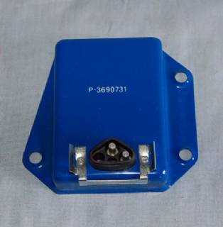
There is no "tip of the triangle." Those regulators only have two connections. That diagram is drawn incorrectly.

P3690731.jpg
 
-
Back
Top