C130 Chief
Mechanical Genius
Take a look at a TH400 style setup, usually on the gas pedal.
Almost ready to do a wiring diagram- The first time delay relay came in and its the cats meow! I'm going to rewire for a second and make some changes from the initial setup.
I've got two questions:
1. I see a people hacking that center piece and using a plate to make the new support, how thick does that piece need to be?
2. what's the difference between the 42rh and a500?
How a material handles load is not all about its thickness. How the material is shaped transfers the load/stress to its other facets. Those 3 and 4 sided elements in the car now are a good example. Their wall thickness is more relative to the attaching hardware used. The majority of it is 11 gauge which is very close to 1/8 wall thickness.
I've got two questions:
1. I see a people hacking that center piece and using a plate to make the new support, how thick does that piece need to be?
2. what's the difference between the 42rh and a500?
Something a few of you have been waiting for I'm sure ;-)
Some notes-
1) Only one hobbs *adjustable* pressure switch is required for this setup, they generally tend to be the most expensive items and you should be using relays anyways since I have seen pressure switches fail from handling the amp load of solenoids.
2) Time delay relays are used for two reasons- Reason one is that pressure switches tend to flutter around the set point and can cause the transmission to rapidly shift back and forth between forth and third, not good. This way once the PSI switch settles down the relay will finally time out (5 to 10 seconds in my case) and you get a solid shift. Note that each time the switch flutters, the timer on the relay restarts! So you will not get a shift till you time out which is a good thing.
You can also extend the mph at which the trans shifts by simply extending the time of the relay- Instead of 5 seconds make it 10 or even 15. I may make it 10 in my case since we get a lot of traffic in this area which floats back and forth in the 45-55 mph range. I could set the pressure switch higher raising the mph point or just set the relay to come on a touch later. I would rather have the relay come on later since my Duster is happy to cruise on the backroads with OD and LU active at 55-60 mph while turning 1700 rpm. The 5.9 has more than enough grunt at this low rpm to pull away without using very much pedal. A 5.2/318 might be want a bit more road speed and a higher mph set point to make up for the less available torque. Your engine, rear end ratio and tire size will determine what works best for you in regards to mph PSI setting and time delay on the relay.
The second reason is it does away with having to have two pressure switches, the lockup time delay relay is keyed into the first relay and makes the car feel like it has a five speed trans (I can hear and feel lockup when it happens) plus it also protects lockup from the same flutter condition that can happen in overdrive. Remember, the timer for the LU relay does not start till the OD relay has timed out and made the shift into OD!
By time delaying the shift it gets you further out of the zone when flutter can happen.
Even if you do get in this zone then you have to just deal with just OD going back and forth and not both at the same time.
For less complexity you could do away with one relay and just have OD and LU come on at the same time, I ran the car for several weeks that way. The relays are dirt cheap though, I picked up three 0-30 second relays shipped with bases for less than what you would pay for a single pressure switch and they even have LED's that show when they are powered up and have timed out.
The dash switch kills everything of course, just a regular 904 at that point ;-) Mine is disguised as a map light switch in the factory location.
I really don't like the vacuum based switch for WOT- If you are undercarbed then at WOT you will draw a vacuum at higher rpm's and overdrive will trip back in! I'll be swapping to a mechanical switch off the carb for this reason since I'm only running a 625 cfm Carter.
Any questions feel free to fire away!! Diagram is in handy 8 x 11 printing format. Red lines indicated 12V+ circuits, black indicate ground side of circuit.
Gary
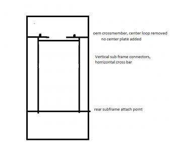
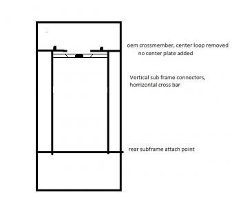
If I may add, sub-frame connectors should negate worrying about replacing the tunnel 'U' piece you cut out, especially with a beefy stock style cross member either fabricated like gdonovan did, or, connecting the cross member into the frame connector in a 'T' type fashion like so:
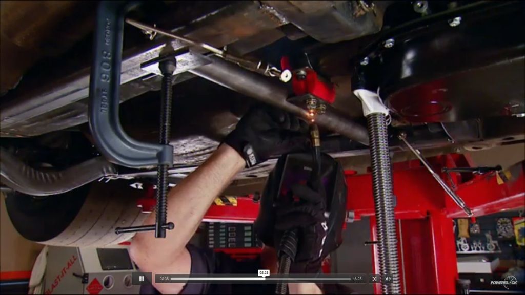
Taken from an episode of powerblockTV stuffing a 426 hemi into a 74' Duster. Crossmember fab comes in at 6 mins or so, which also gives detail on wall thickness of steel used:
http://www.powerblocktv.com/player/show_player.php?ep_show=MC&ep_num=MC2012-11
I've gonna say, if it's strong enough for a 426 new Hemi, it's strong enough for a 360 running a 42RH. :glasses7:
:burnout:
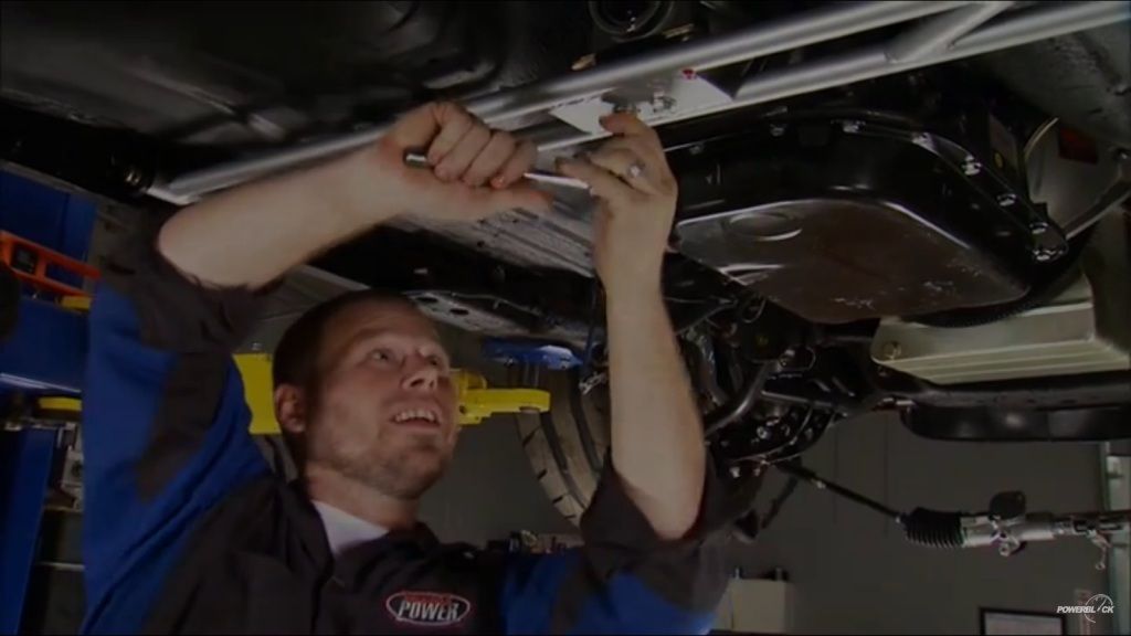
Also found another style of cross member fab on this episode:
http://www.powerblocktv.com/player/show_player.php?ep_show=HP&ep_num=HP2012-07
Hopefully this isnt construed as hijacking, i think its still pertinent to the 42rh swap.
One more Q: is there a size difference from the 42rh/46rh or is it just different internals?
But is that stiff enough for us using who are still using t-bar suspension? They went alterkation on that dart sport.
you say "into a "T", but wouldnt an H be more appropriate?

Do you have a list of parts and part #'s and where you got them?
Thanks.
Late to the party as usual, I would like to know what you did for the trans lines to the radiator/trans cooler? Did you use the factory type fittings or go to the old school compression fittings like our 60's and 70's cars used?
Also, I would really like to see what you did to the trans internally. I looked for a thread covering it but did not find one.


