fishy68
Tyr Fryr's Inc.
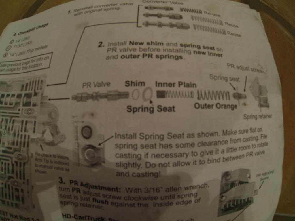
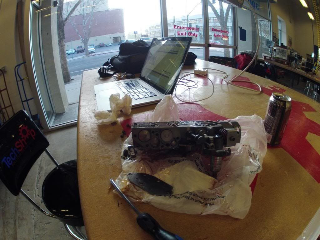
Alright here we go
.I believe everything looks right there
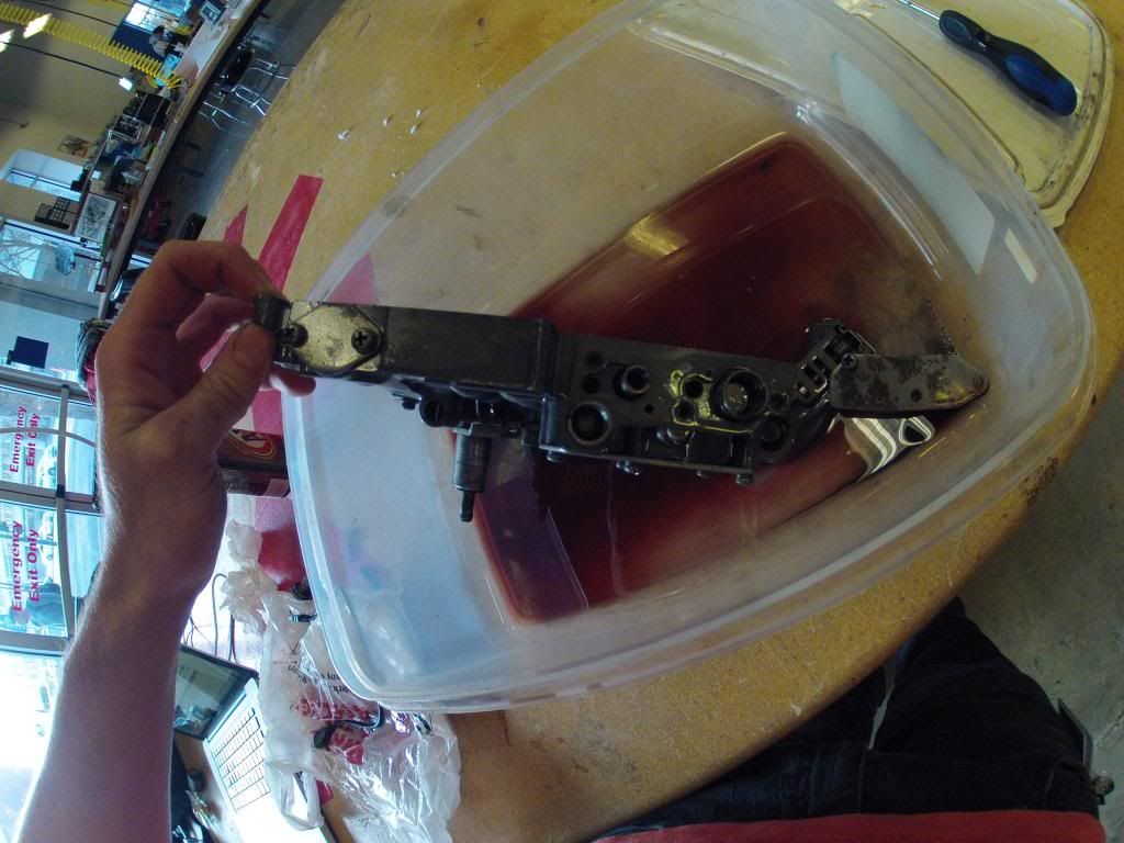
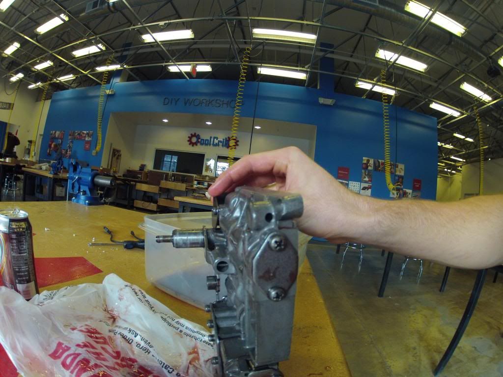
All looks ok here
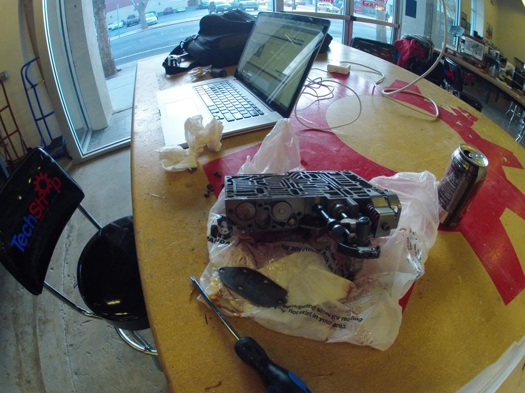
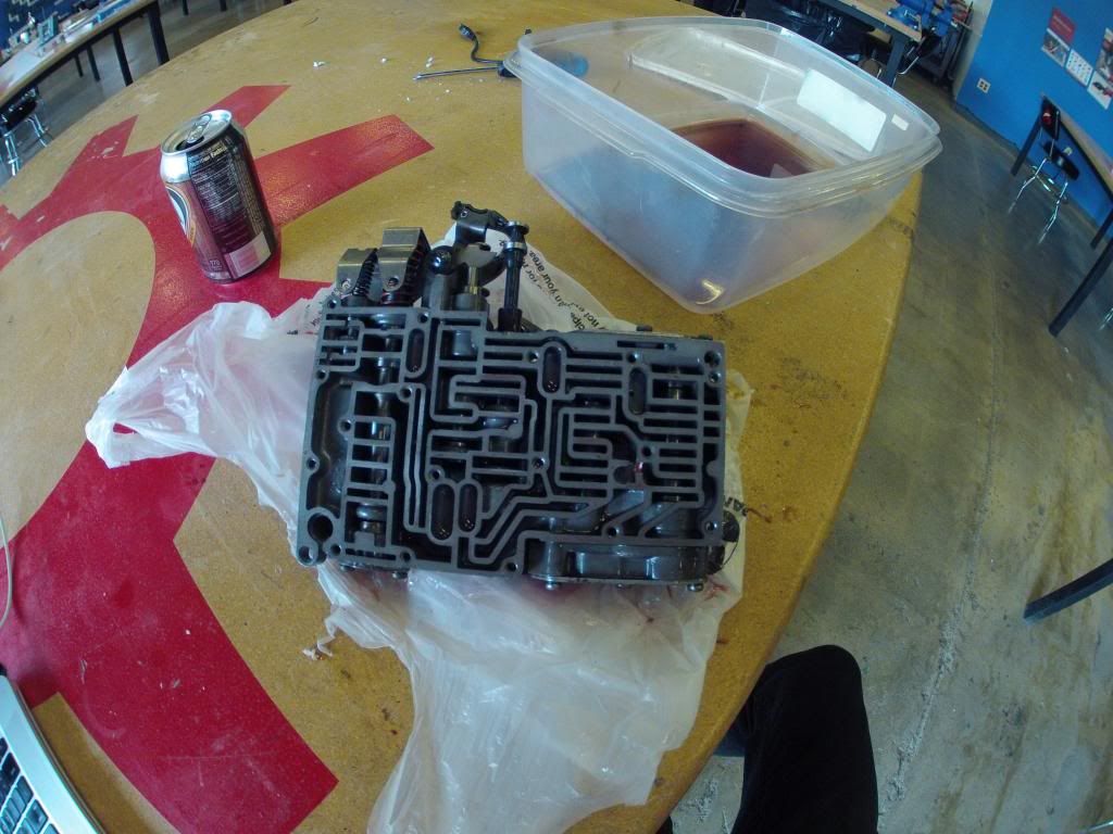
Looks ok here
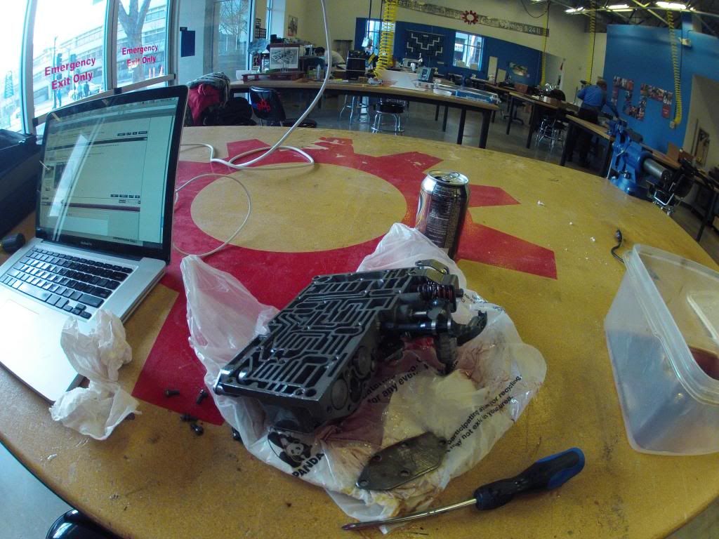
I see 2 possible problems here. Both check ball related. Why isn't there a check ball in the upper right check ball channel? Also what size is the check ball in the larger check ball channel in the mid to lower left side? Should be a 11/32" diameter check ball. Looks like you have a 1/4" check ball in there.
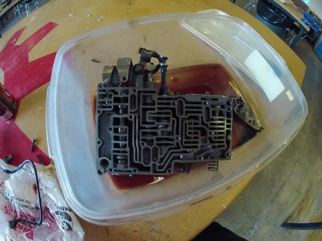
I posted under each picture thoughts I had on what I saw. The only possible problem(s) I saw are the check ball issues I asked about. I don't know what would happen if the upper right check ball was left out and the lower left one is smaller than it's supposed to be but I'd bet dollars to dimes it'd cause a problem.